EIR3D
Handcrafted • Detailed • Unique

Institutional Engineering Platform

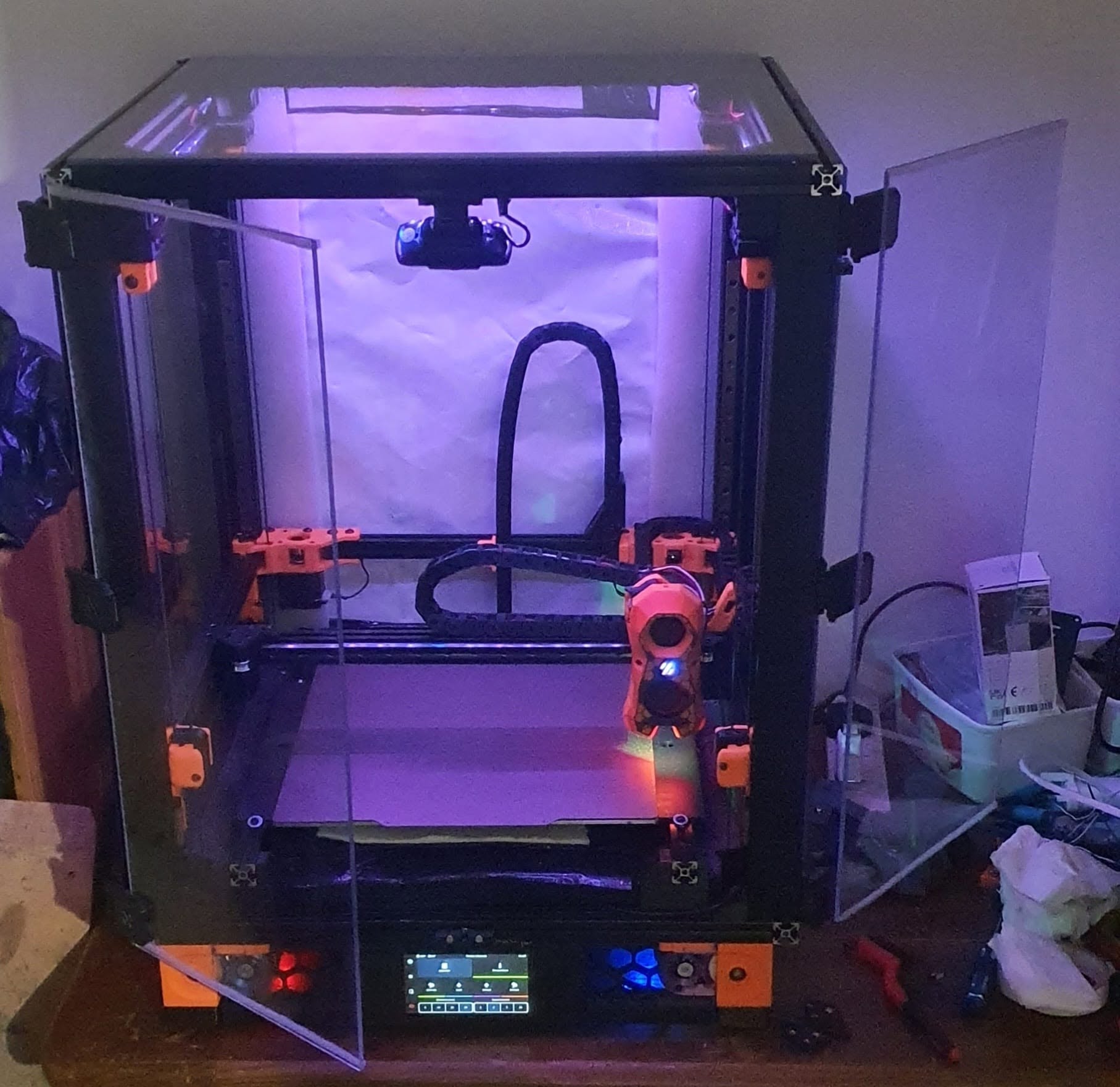
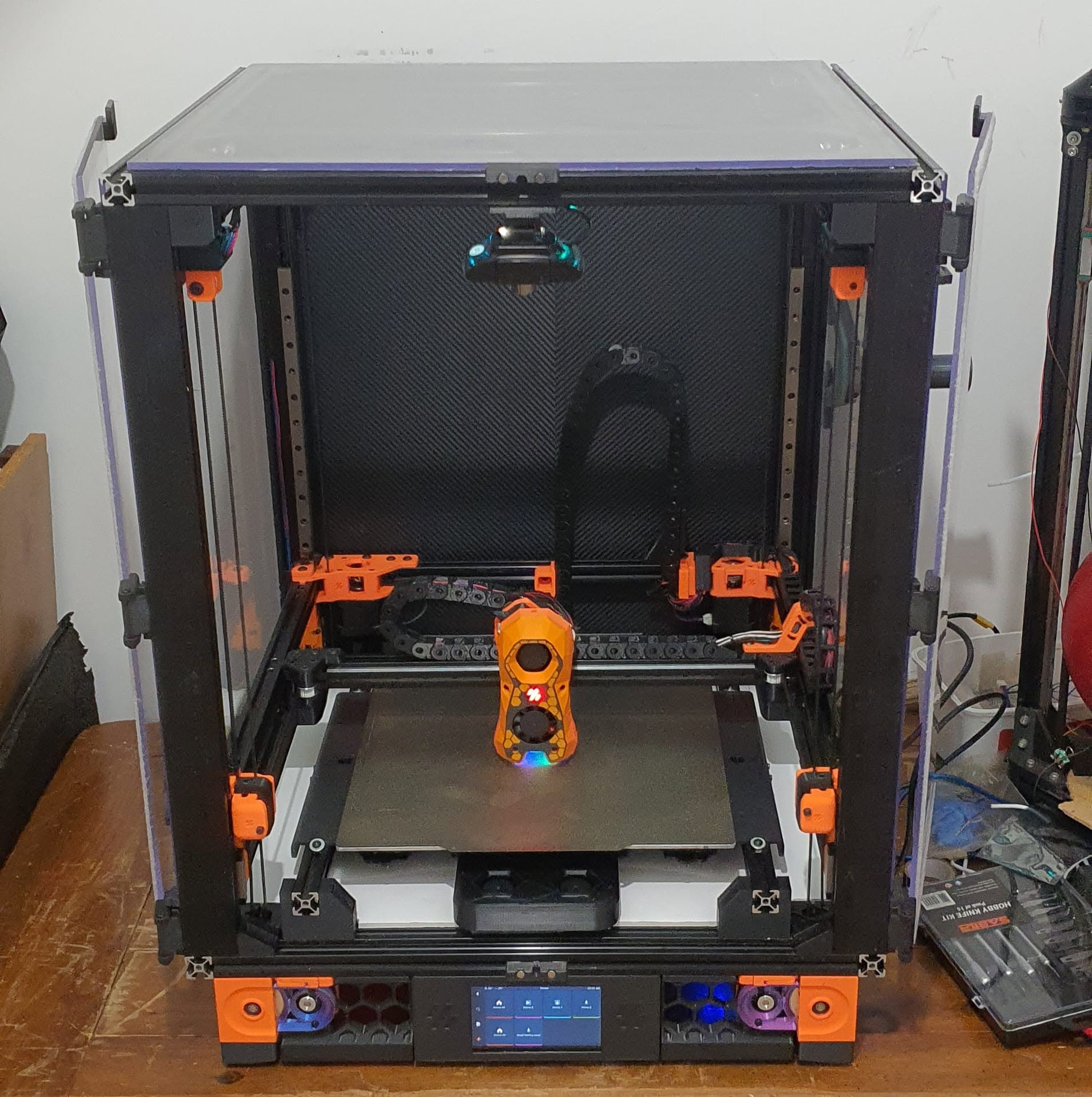
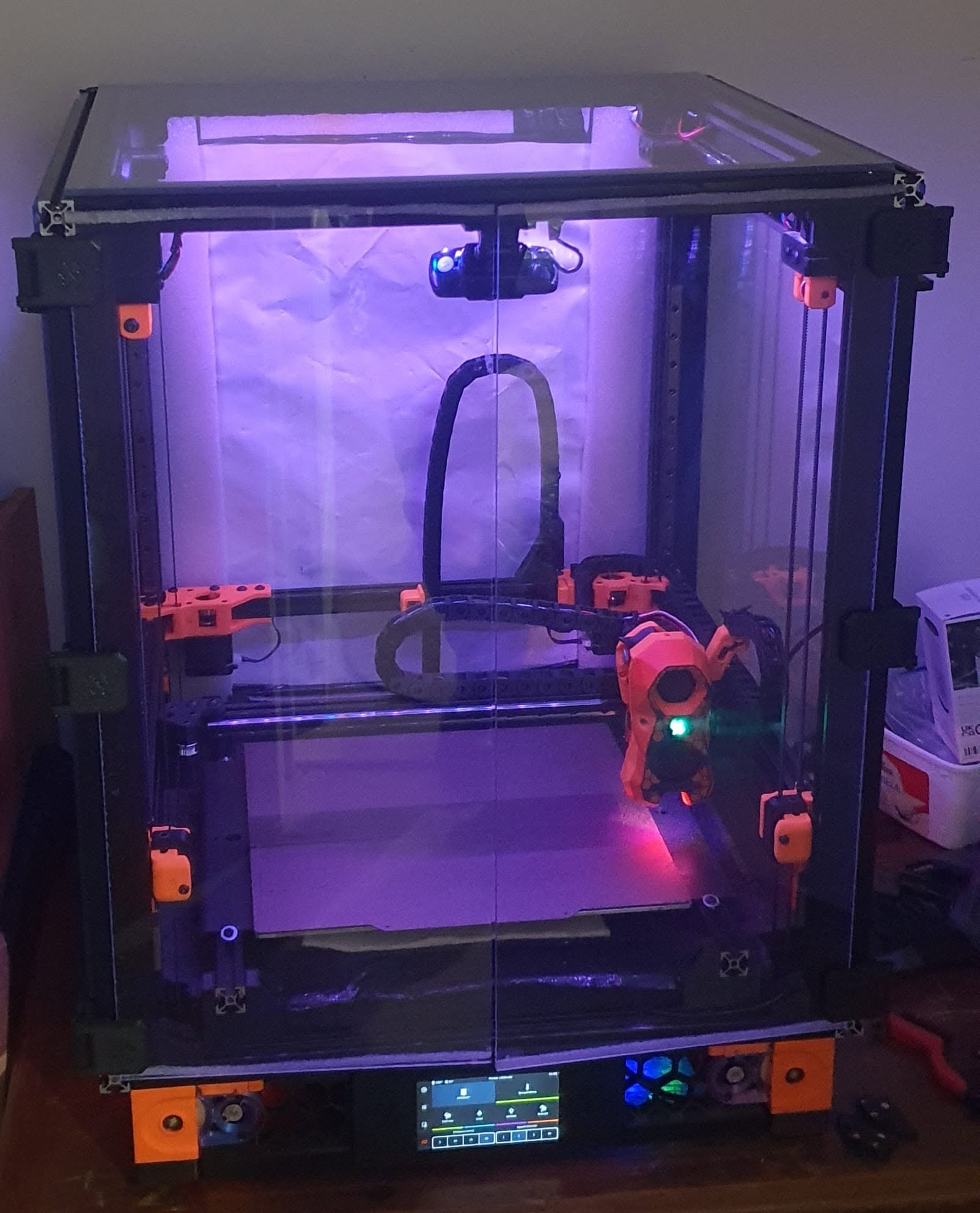
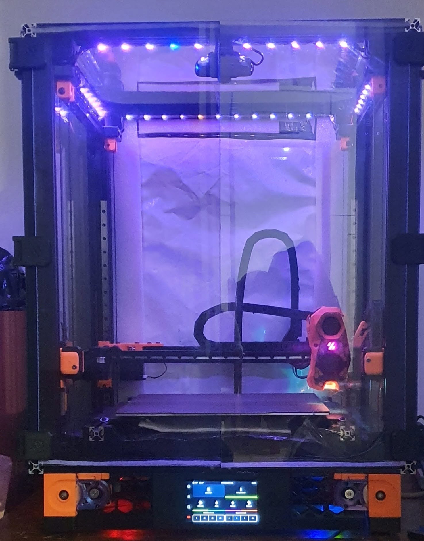
True engineering supersedes consumer appliance design. Explore our flagship commercial-grade, fully enclosed CoreXY system—custom-engineered with open-source firmware architecture specifically tailored to govern this exact machine's kinematics, distributed CAN-bus electronics, and thermal profiles.
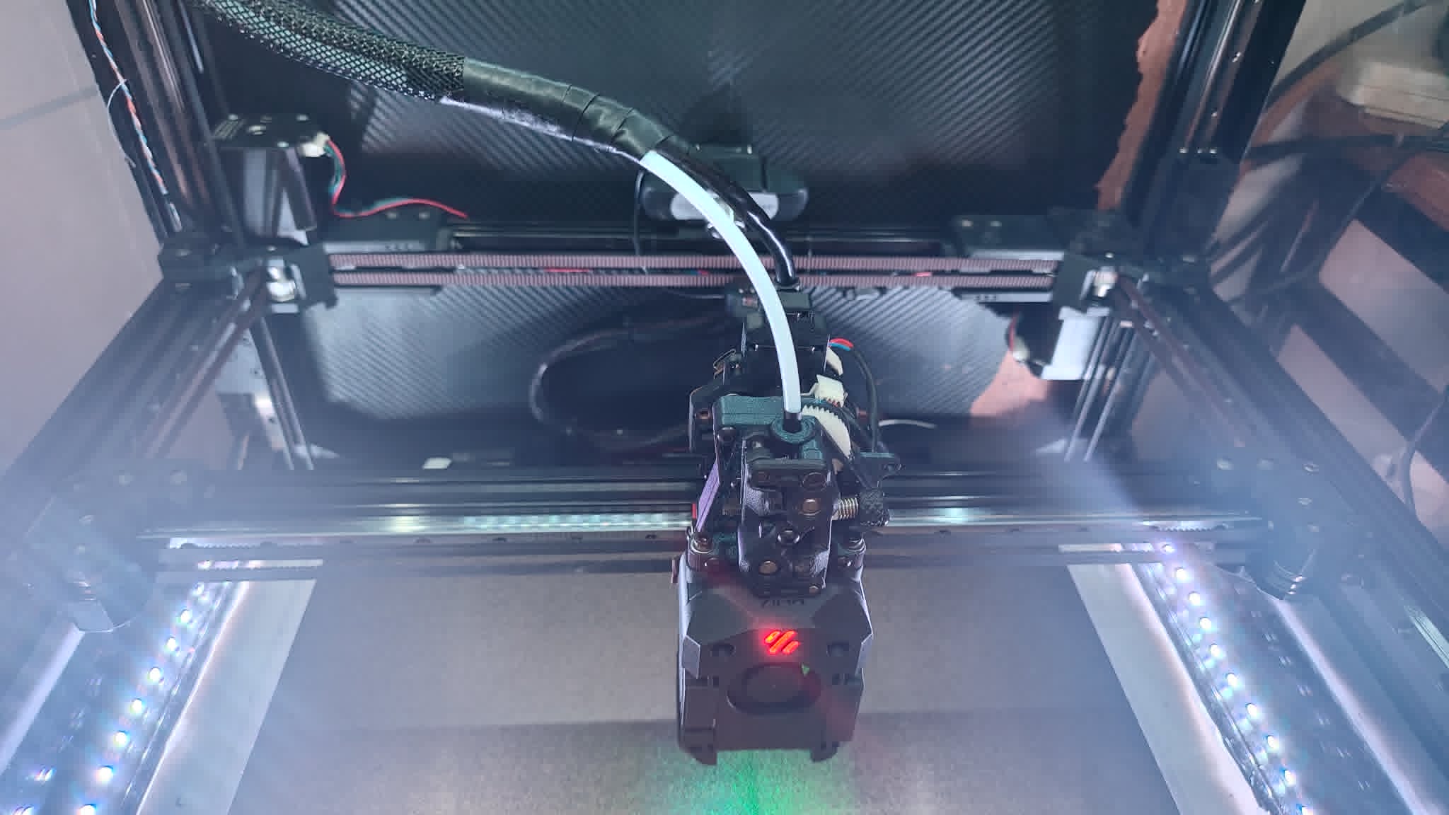
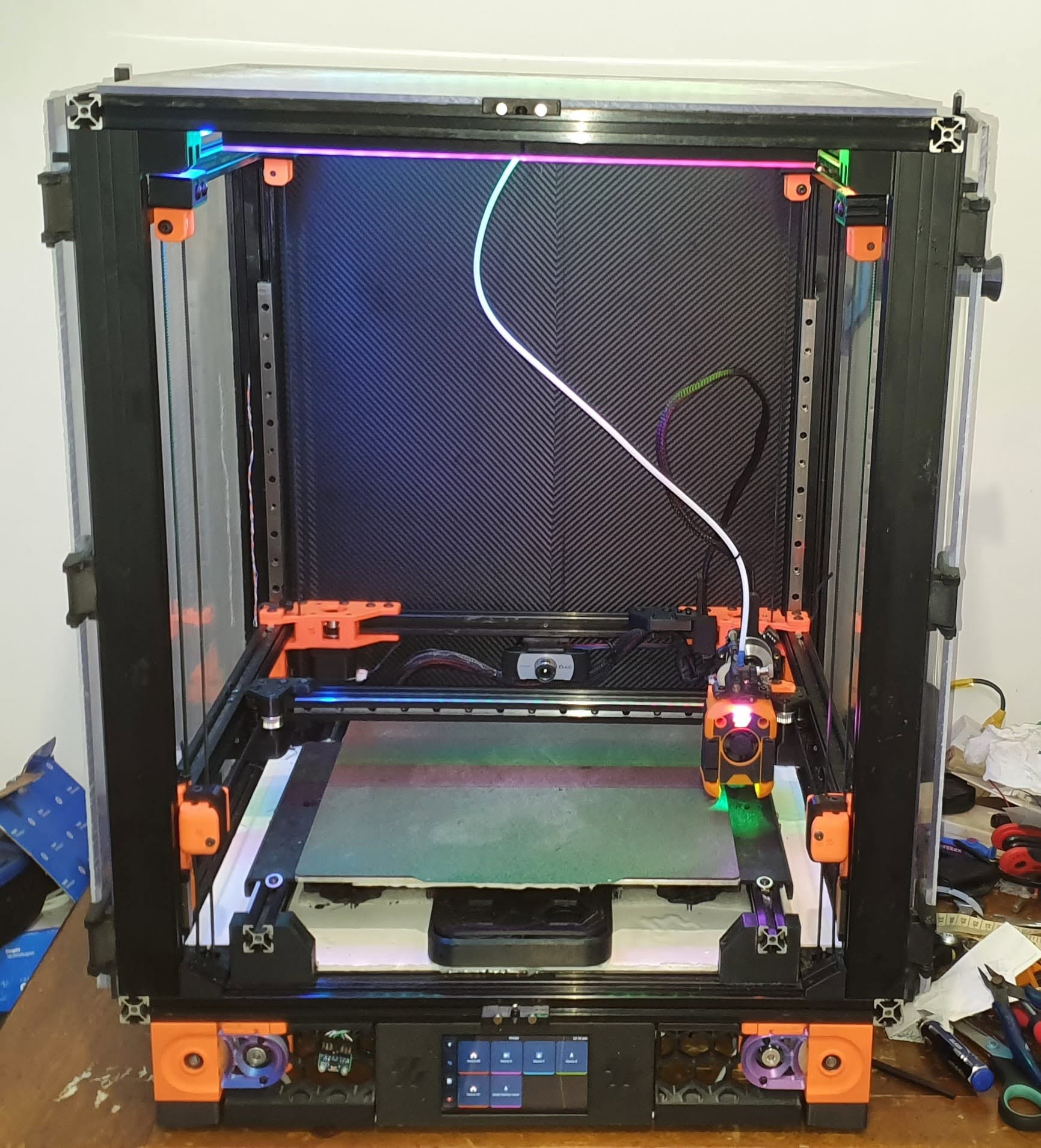
Eir3D Fully Enclosed Commercial-Grade CoreXY System
Advanced Mechatronics • Open-Source Firmware Architecture

The Eir3D Commercial-Grade CoreXY Architecture

Developed as an uncompromising alternative to off-the-shelf consumer kits, this machine represents a masterclass in custom mechanical engineering and bespoke open-source programming. Controlled entirely by an open-source, custom-tailored programming configuration written specifically for this hardware topology, it provides deep insight into micro-controller communication, kinematic math, and real-time process control ideal for advanced technical education.

Comprehensive Technical Specifications

System Classification Fully Enclosed, Custom-Programmed Commercial-Grade CoreXY Production & Educational Platform
Open-Source Programming Bespoke open-source firmware configuration written and optimized exclusively for this machine's exact kinematic layout, custom macro routines, thermal safety algorithms, and closed-loop feedback loops.
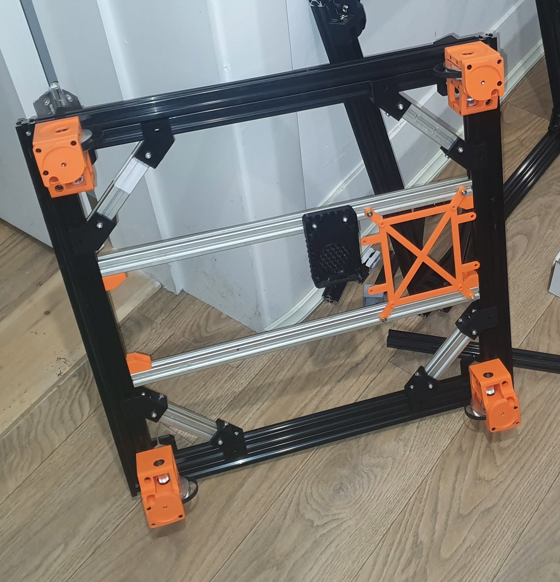
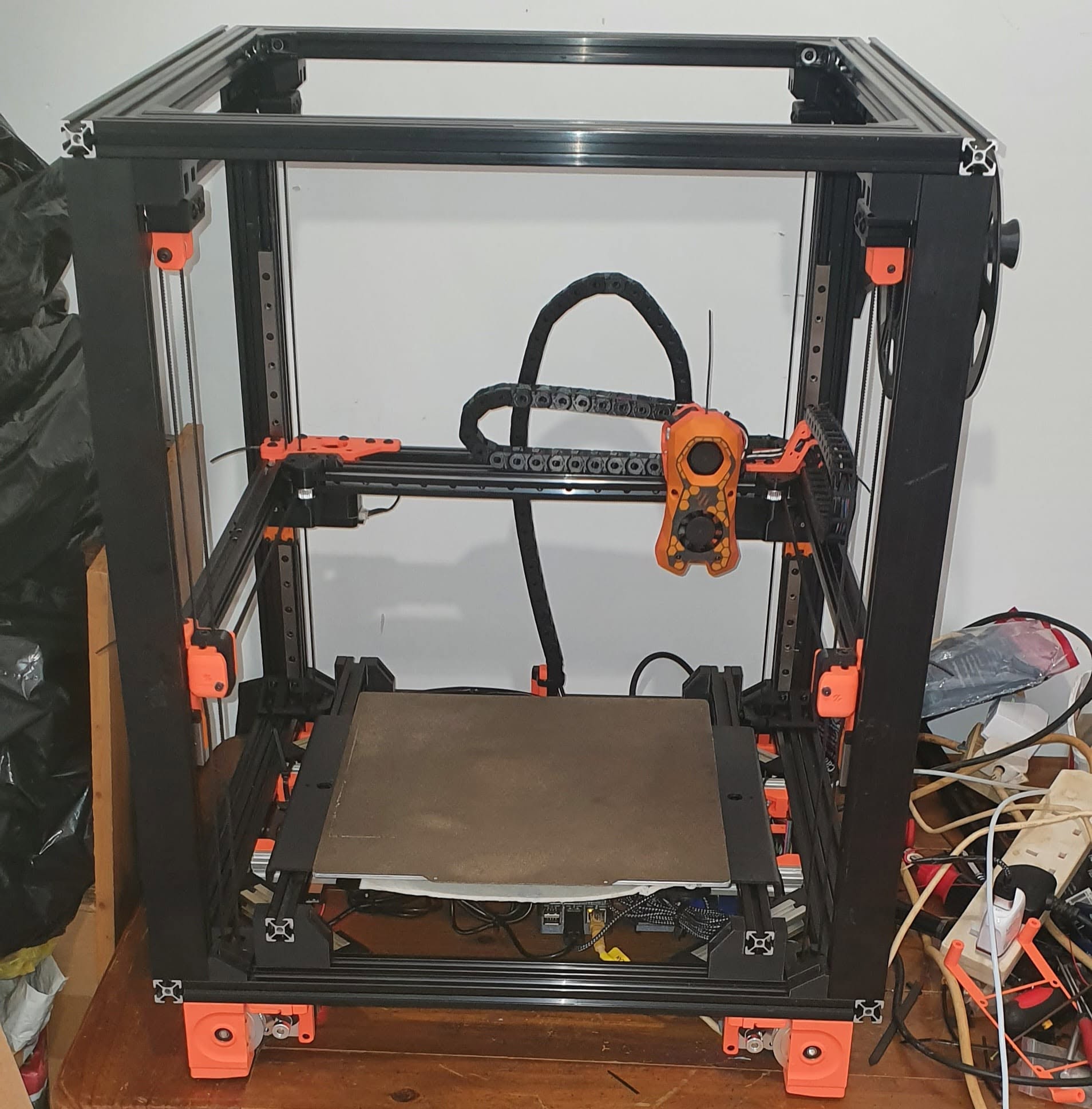
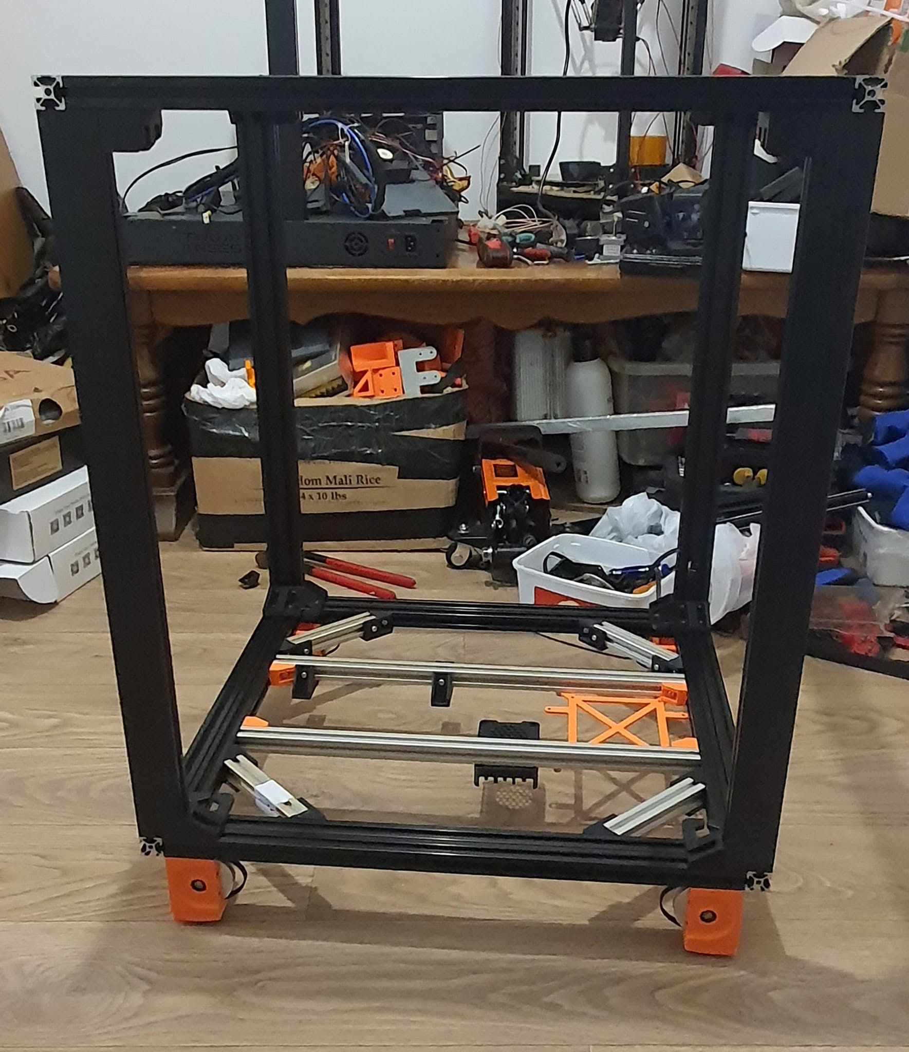
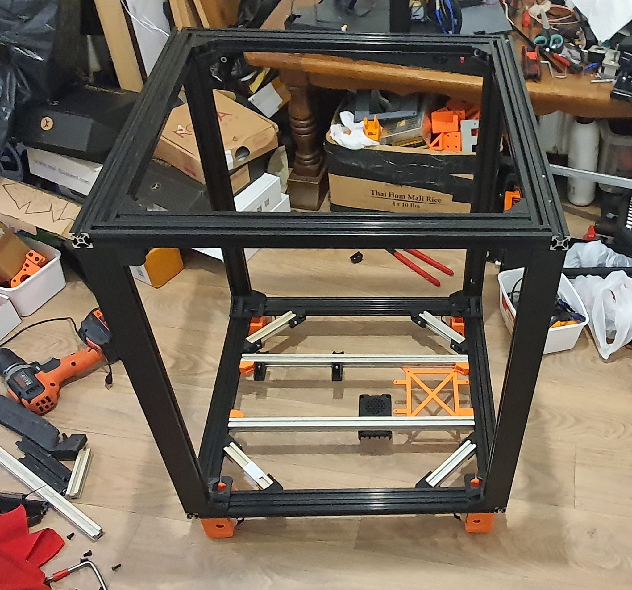
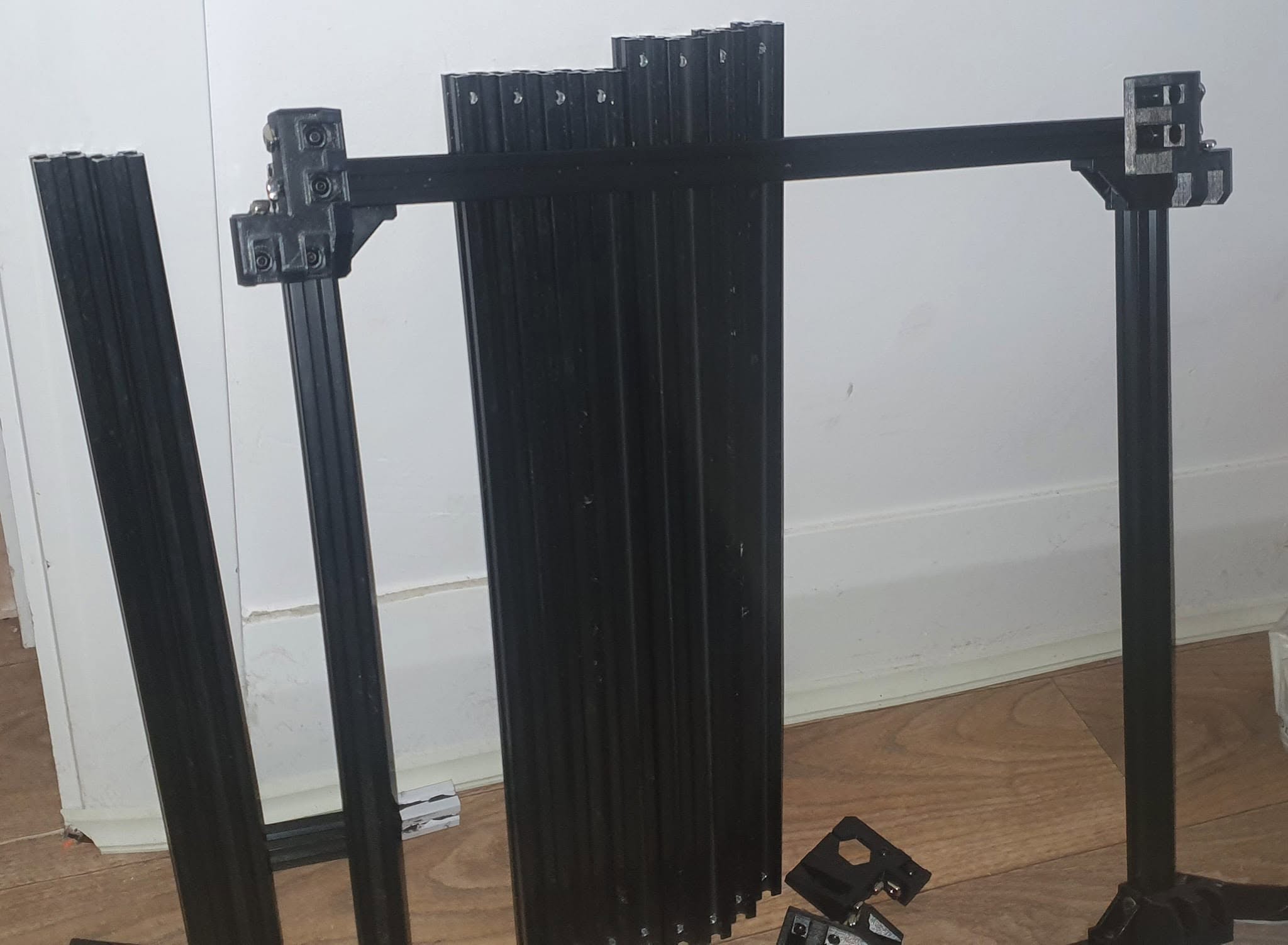
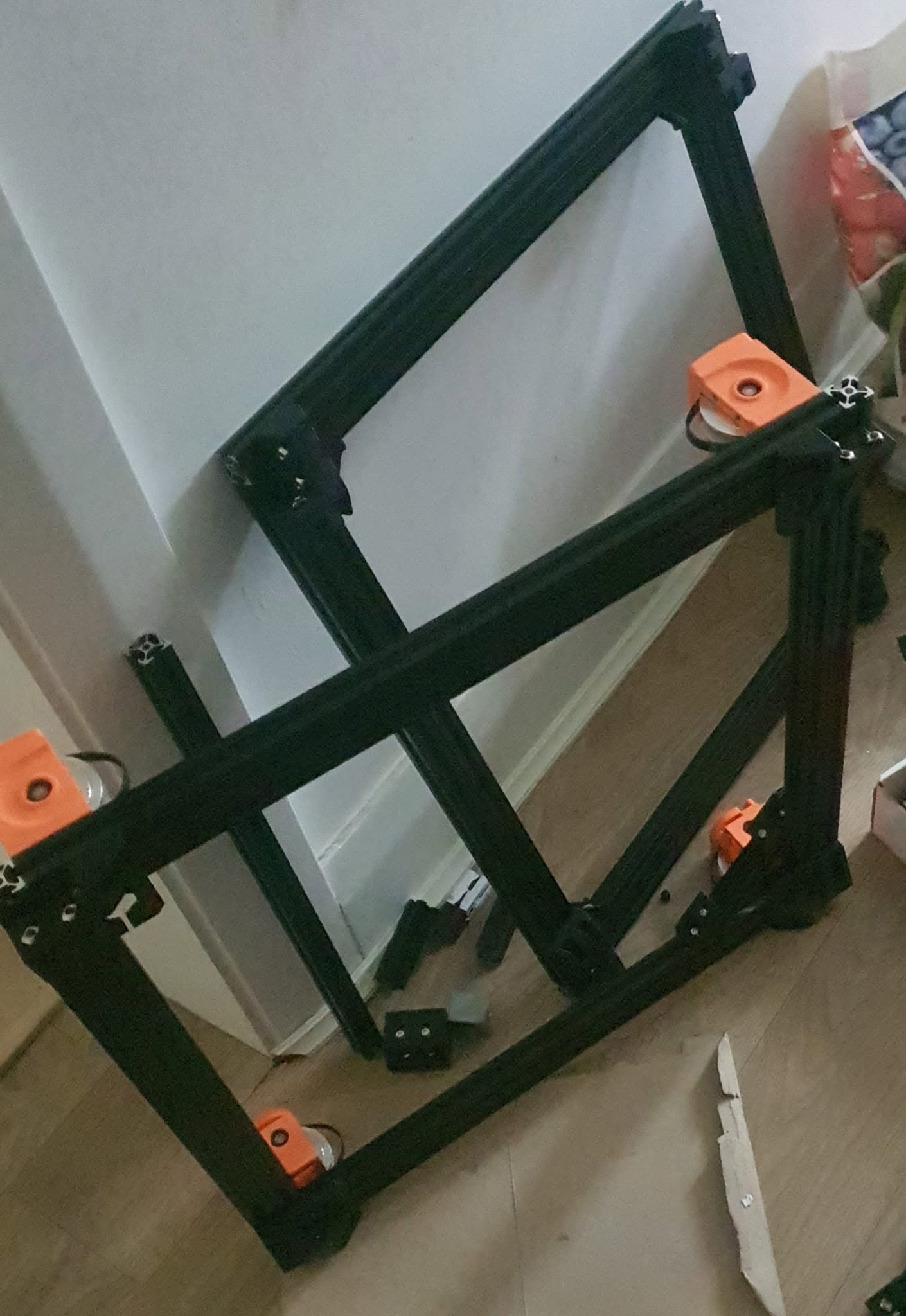
Chassis & Frame Engineering Ultra-rigid, un-twistable frame constructed from 4x 2040 Z-beams and 16x 2020 extrusions integrated into 8x 2040 interlocking members. Reinforced with heavy-duty ABS printed corner brackets and secured by 21 M5 high-tensile bolts with Misumi slot-in T-slot nuts per corner, yielding structural rigidity comparable to high-specification industrial CNC systems.
Build Platform & Bed Assembly Precision-milled MIC6 350mm x 350mm x 8mm tooling plate paired with a 350mm x 350mm spring steel sheet secured via a high-performance magnetic top surface. Supported by heavy-duty Z-drive brackets with industrial GE5C spherical bearings and custom waffle-pattern TPU pads to isolate and absorb high-frequency vibration distributions.
Thermal & Enclosure Management Fully enclosed thermal chamber engineered for high-temperature engineering-grade materials processing, equipped with 2x recirculating activated carbon filter fans for active chamber air filtration. Powered by a 750W 230V silicon build plate heater governed safely by a 24V signal through an iAutoc 25A solid-state relay (SSR) featuring an integrated 135°C safety thermal fuse.
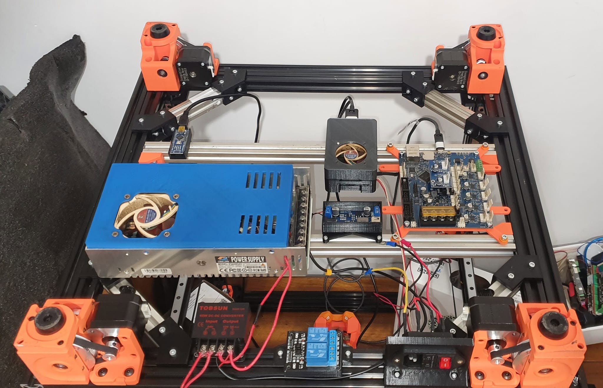
Processing & Core Control Powered by a Raspberry Pi 5 (4GB) running custom-configured open-source host software, communicating with a BigTreeTech Octopus Pro v1.1 H723 (550MHz MCU) motherboard utilizing 6x TMC2209 stepper drivers operating in silent UART mode.
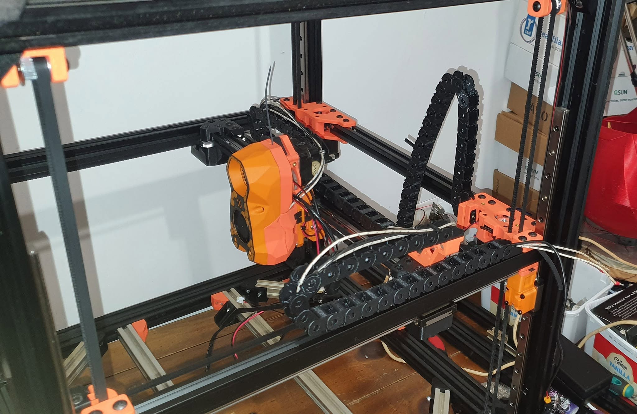
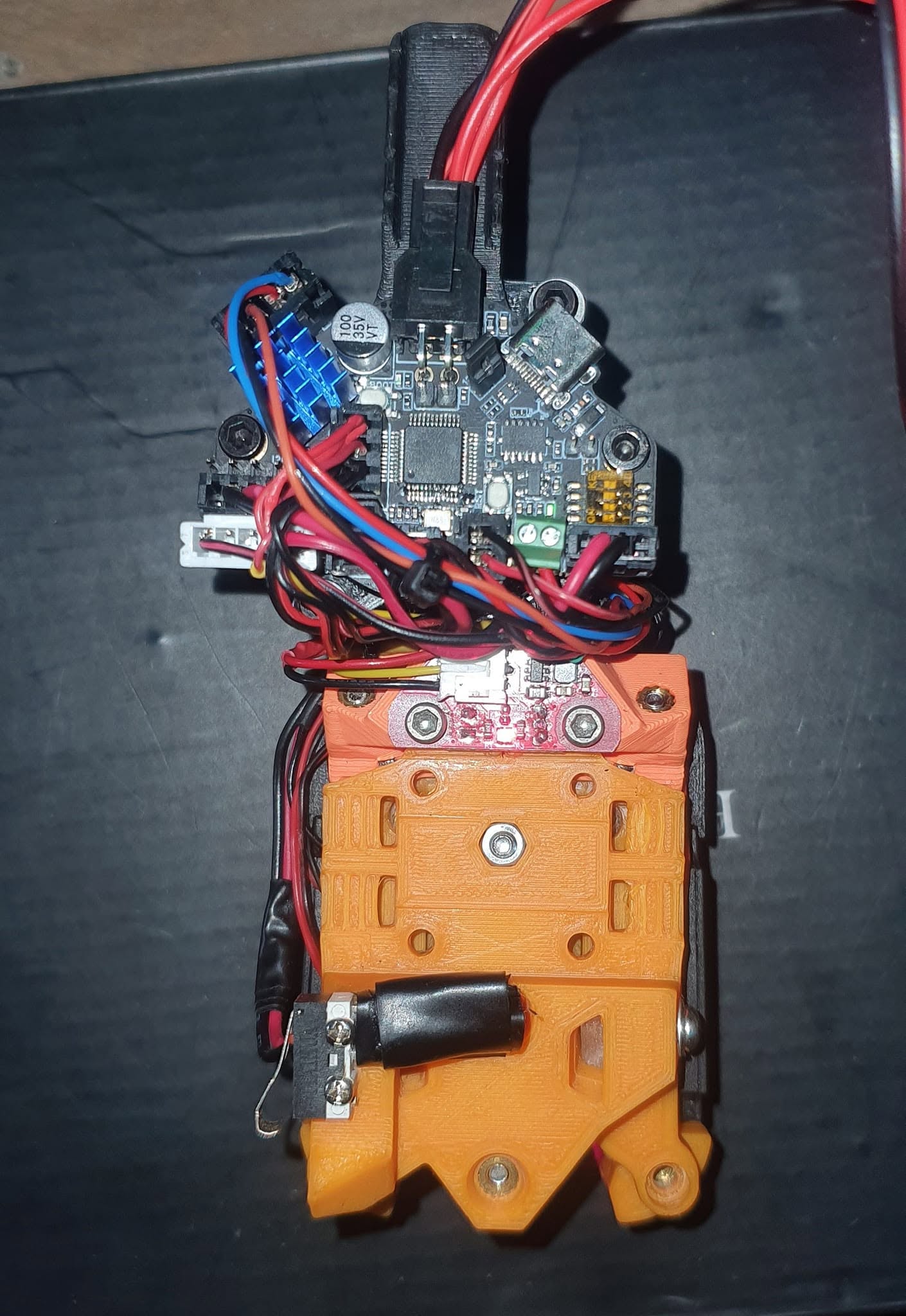
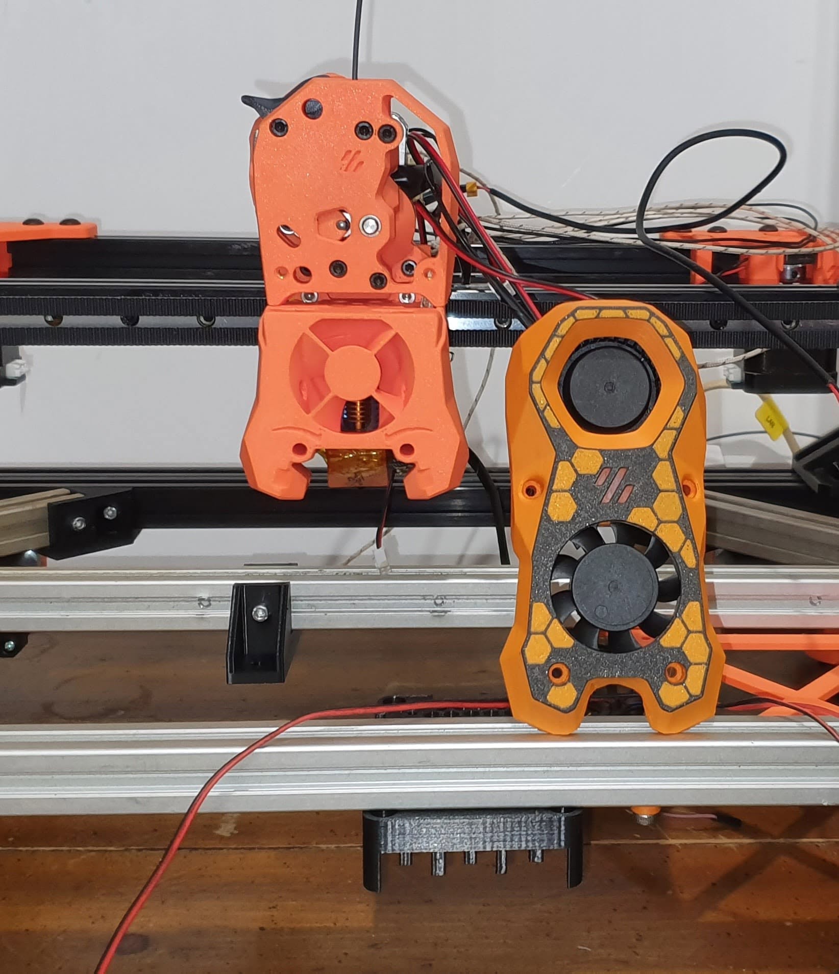
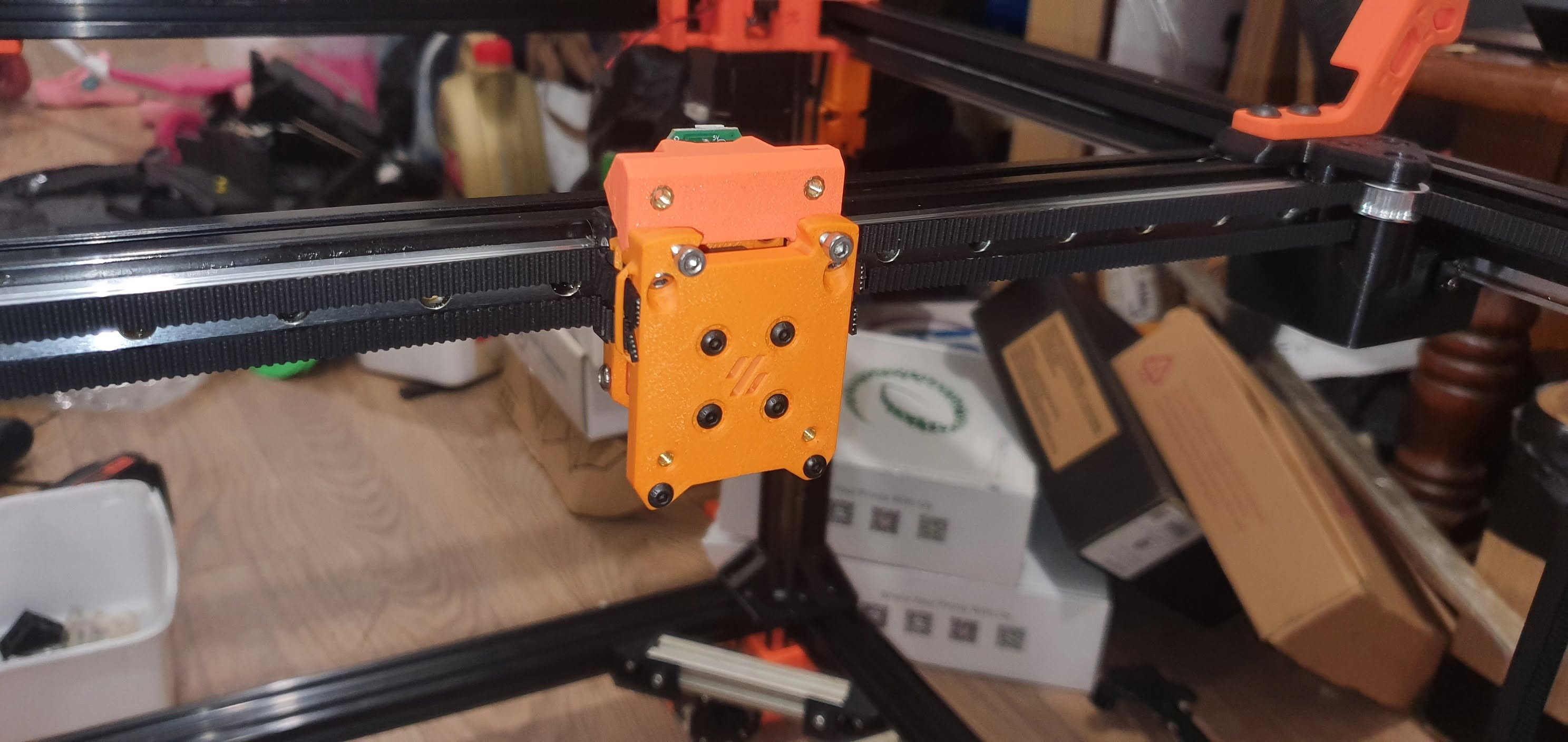
Toolhead & Extrusion Mechanics Decentralized H36 toolhead board controlling printhead electronics via reliable CAN-bus architecture from the main MCU. Equipped with a Phaetus Rapido v2 Ultra High Flow hotend and a dual-stage dual-gear direct-drive extrusion system designed for maximal filament grip and torque.
Motion Kinematics & Gantry Driven by LDO Speedy Power XY motors on a carbon-fiber reinforced ASA monolithic gantry. Linear motion is governed by a precision single MGN12H rail on the X-axis, dual MGN9H rails on the Y-axis, and quad MGN12H rails on the Z-axis, featuring upgraded GE5C spherical Z-joints for zero-binding vertical motion.
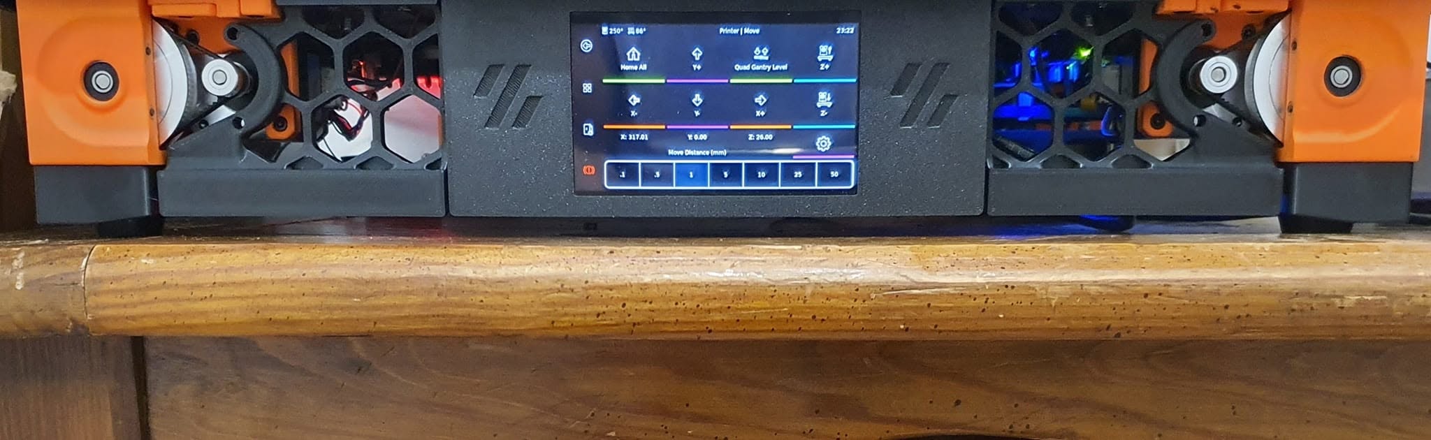
Calibration & User Interface Integrated Cartographer Eddy Current Sensor for ultra-fast, high-precision non-contact bed mapping, managed through an intuitive 5-inch touchscreen control console.

The Institutional Educational Pipeline

01. Open-Source Custom Code

Analyzing bespoke configuration files, pin mapping, macro programming, and firmware compilation specific to custom hardware arrays.

02. Structural Rigidity & Mechanics

Demonstrating CNC-grade frame design, interlocking profile mechanics, and mechanical vibration isolation principles.
03. Electrical Safety & Control

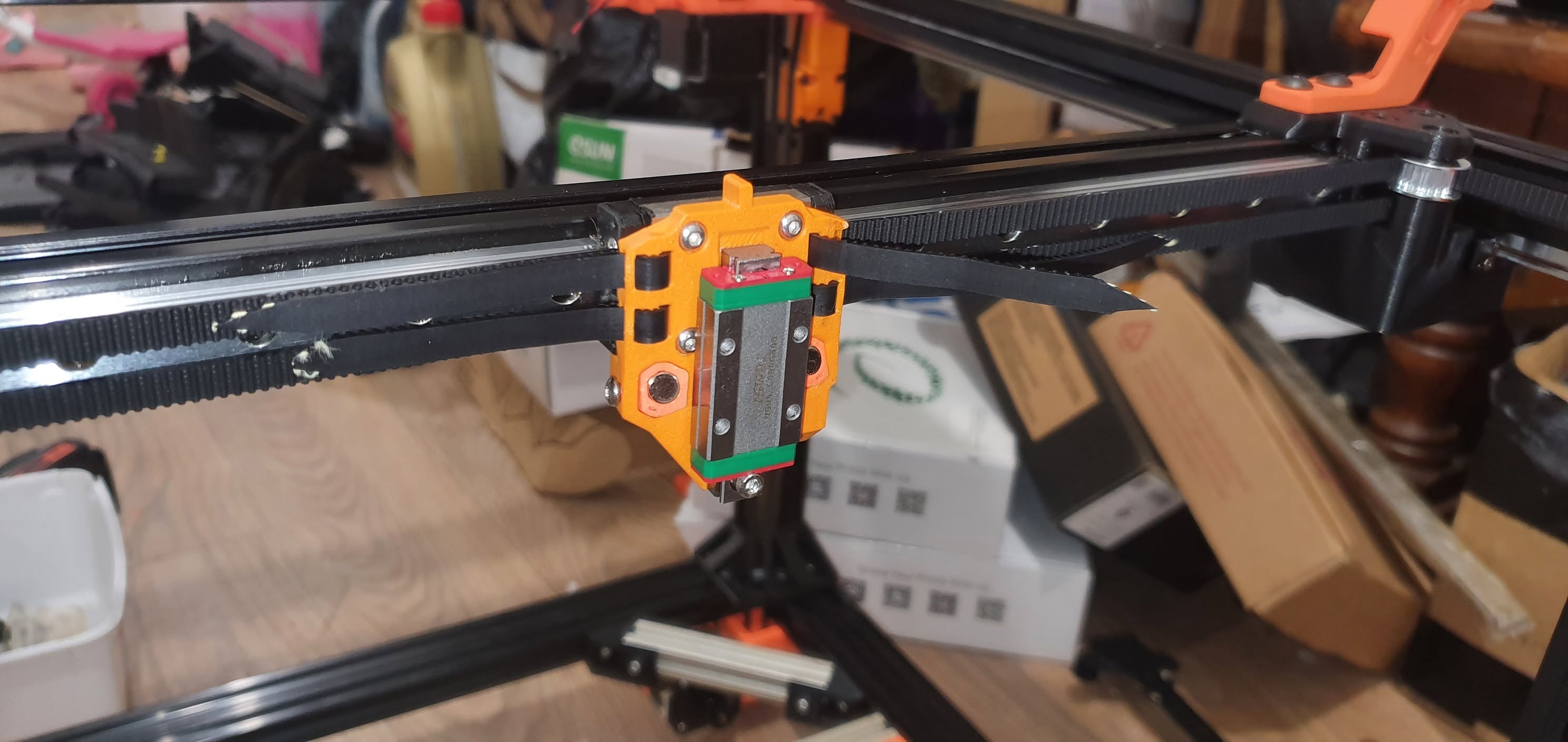
Teaching high-voltage (230V) switching, solid-state relay integration, thermal fusing, and distributed CAN-bus networking.

04. Thermal Science & Polymers

Exploring chamber thermodynamics, air filtration safety via dual carbon filter fans, and processing parameters for high-temp thermoplastics (ASA-CF).

Key Engineering Highlights

  • Proprietary open-source software configuration tailored explicitly to run this machine's exact kinematic layout, providing students with pure transparency into machine-level programming.
  • Commercial-grade structural integrity featuring an 8mm thick precision-milled MIC6 tooling plate and 750W high-power heating elements equipped with thermal fuse safety backups.
  • Un-twistable, high-rigidity frame architecture featuring interlocking 2040 profiles, heavy-duty ABS brackets, and Misumi hardware comparable to CNC industrial standards.
  • Fully enclosed thermal chamber equipped with dual recirculating activated carbon filter fans, optimized for safe, high-temperature engineering-grade material processing.
  • Advanced distributed control architecture combining a 550MHz Octopus Pro MCU, Raspberry Pi 5, and clean CAN bus toolhead routing.
1 / 40
270 Degree Doors Hinges

01. 270 Degree Doors Hinges

Initial mechanical build phase and framework alignment.

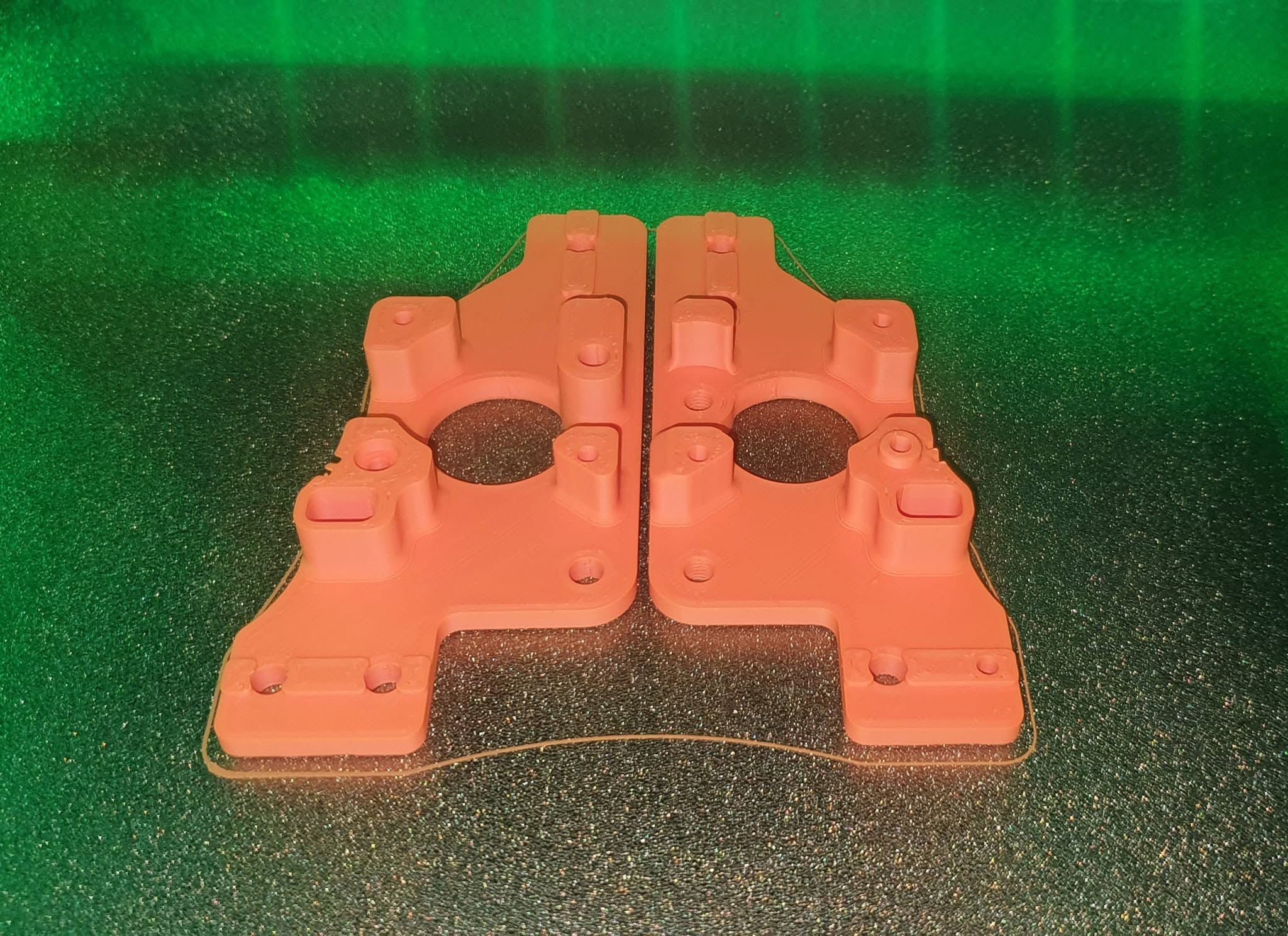
A Drive Motor Mount Printed

02. A Drive Motor Mount Printed

Initial mechanical build phase and framework alignment.

B Drive Motor Mount

03. B Drive Motor Mount

Initial mechanical build phase and framework alignment.

B Drive Motor Mount Rear

04. B Drive Motor Mount Rear

Initial mechanical build phase and framework alignment.

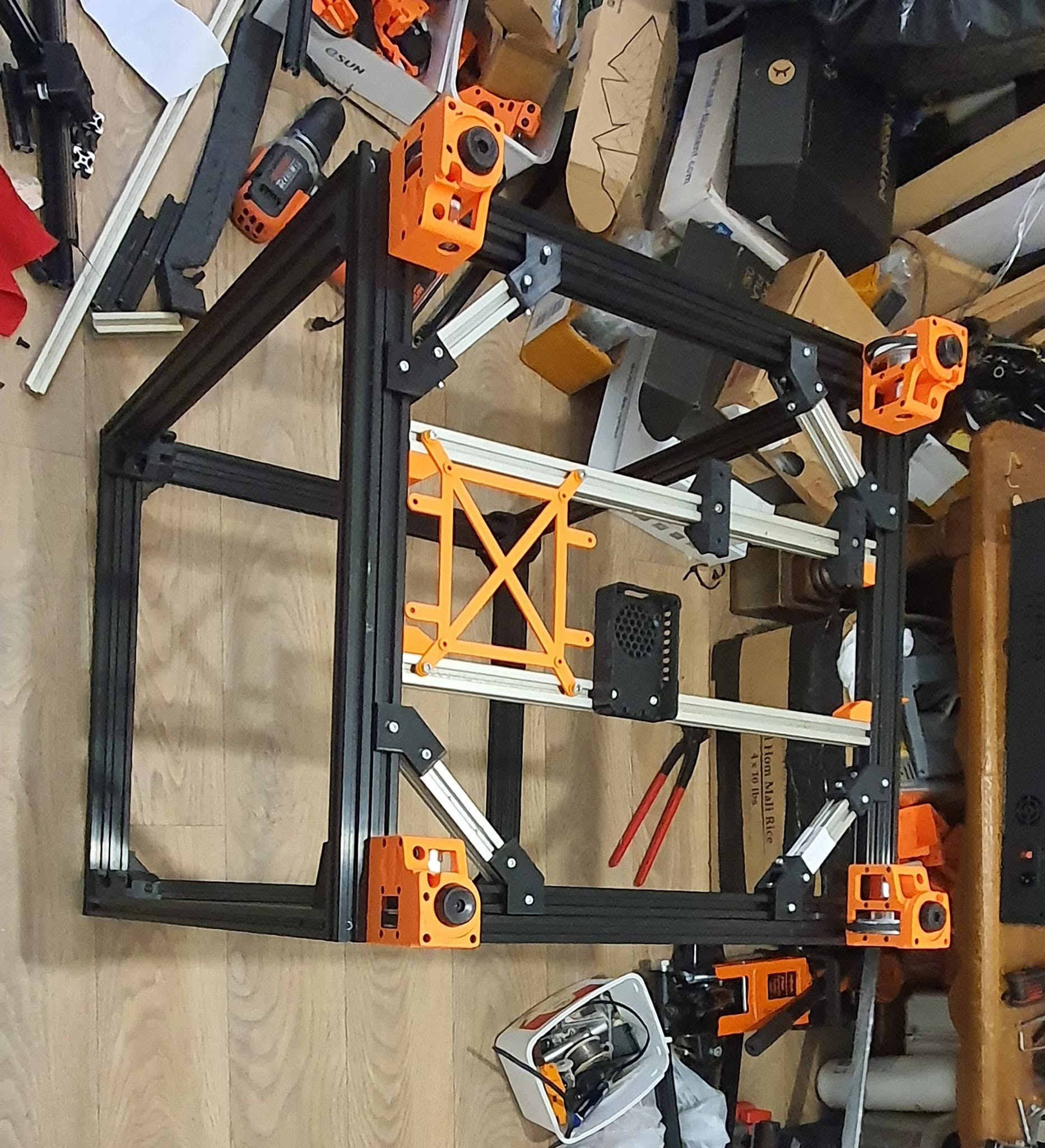
Bottom Frame With MCU Board Mountings

05. Bottom Frame With MCU Board Mountings

Initial mechanical build phase and framework alignment.

Bottom Panel Fitted

06. Bottom Panel Fitted

Initial mechanical build phase and framework alignment.

Buildplate Fitted

07. Buildplate Fitted

Initial mechanical build phase and framework alignment.

Cable Chain Fitted

08. Cable Chain Fitted

Initial mechanical build phase and framework alignment.

Canbus Board Upgrade

09. Canbus Board Upgrade

Initial mechanical build phase and framework alignment.

Control Interface Testing

10. Control Interface Testing

Initial mechanical build phase and framework alignment.

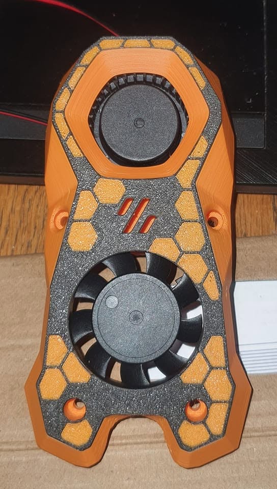
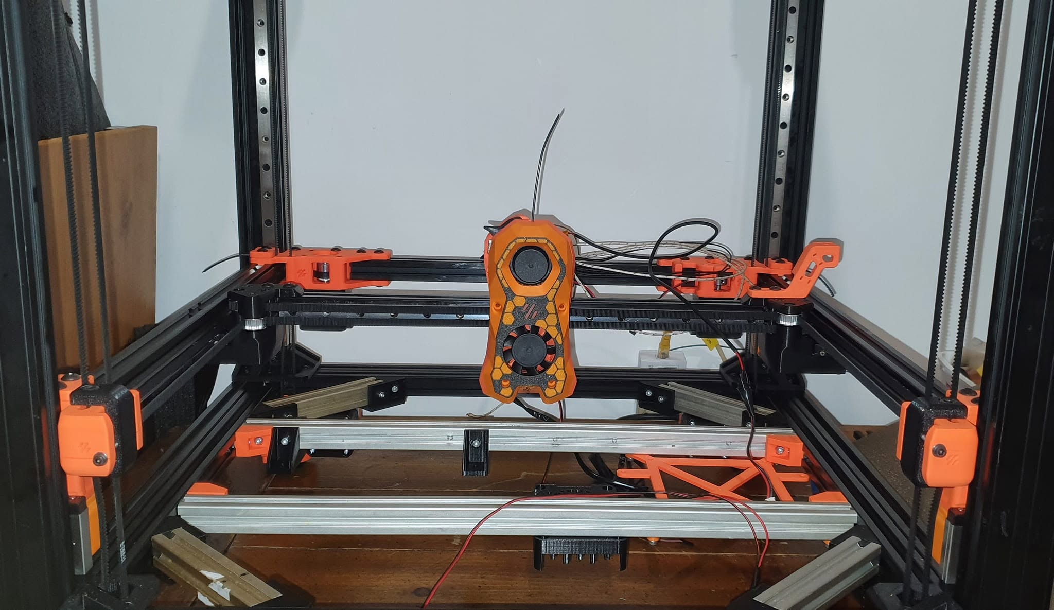
Dual Color Toolhead Cover

11. Dual Color Toolhead Cover

Initial mechanical build phase and framework alignment.

Dual Color Toolhead Cover Completed

12. Dual Color Toolhead Cover Completed

Initial mechanical build phase and framework alignment.

Enclosure Fitted

13. Enclosure Fitted

Initial mechanical build phase and framework alignment.

First Bench Test

14. First Bench Test

Initial mechanical build phase and framework alignment.

First Test Print XY Axis Angle

15. First Test Print XY Axis Angle

Initial mechanical build phase and framework alignment.

First Test Print Y Axis Side

16. First Test Print Y Axis Side

Initial mechanical build phase and framework alignment.

Frame Completed Bottom Side With Z Drives

17. Frame Completed Bottom Side With Z Drives

Initial mechanical build phase and framework alignment.

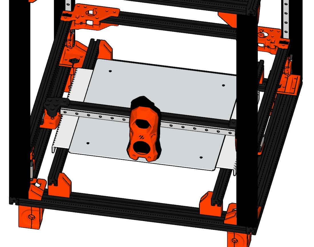
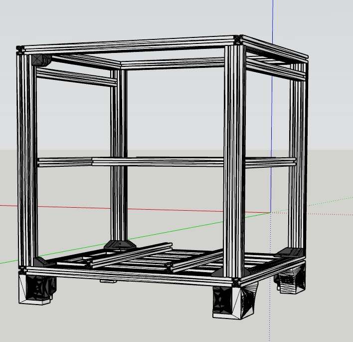
Frame Design CAD Drawing

18. Frame Design CAD Drawing

Initial mechanical build phase and framework alignment.

Frame With Gantry Mounted

19. Frame With Gantry Mounted

Initial mechanical build phase and framework alignment.

Frame With Z Axis Components Mounted

20. Frame With Z Axis Components Mounted

Initial mechanical build phase and framework alignment.

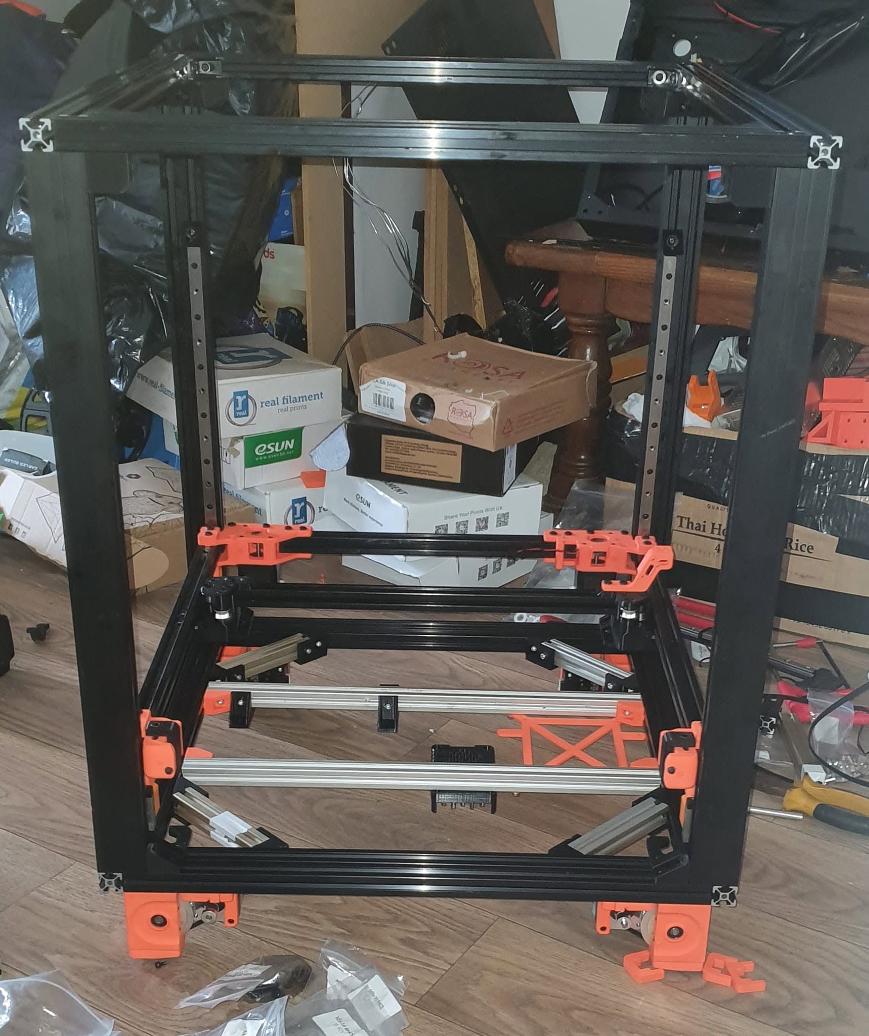
Front Of Complete Frame Assembly

21. Front Of Complete Frame Assembly

Initial mechanical build phase and framework alignment.

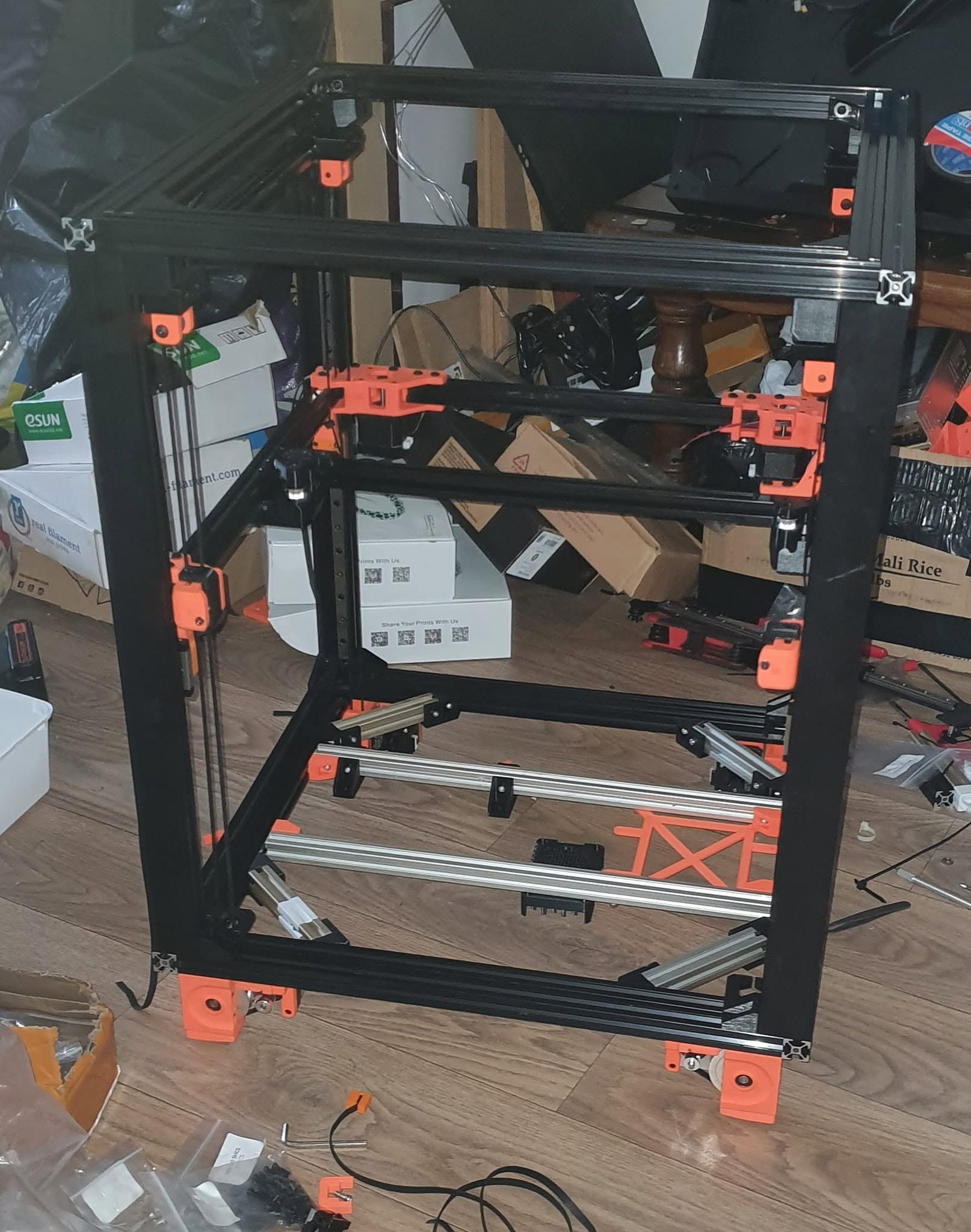
Full Frame Demostrating Interlocking Sections

22. Full Frame Demostrating Interlocking Sections

Initial mechanical build phase and framework alignment.

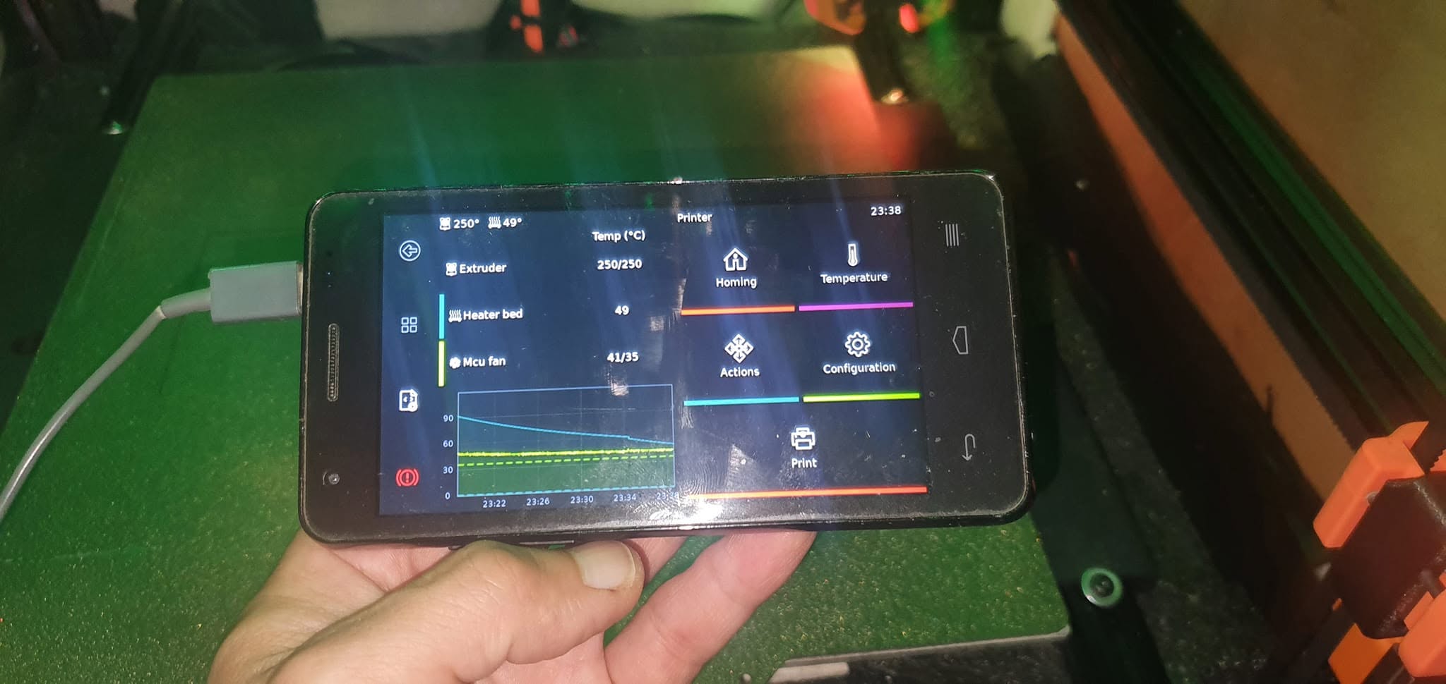
LCD Control Converted From Old Android Phone

23. LCD Control Converted From Old Android Phone

Initial mechanical build phase and framework alignment.

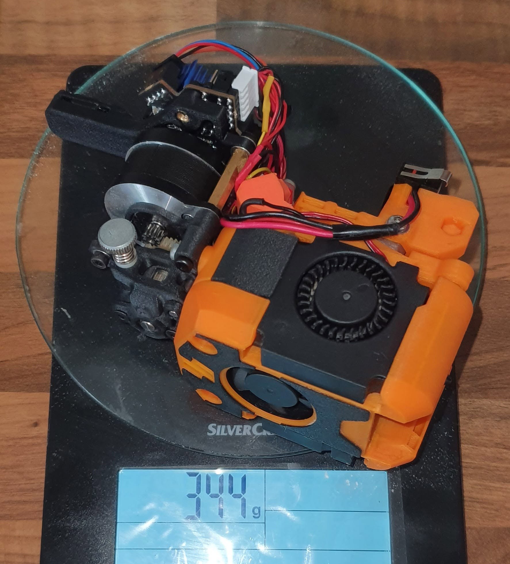
Light Weight Toolhead And Canbus Installed

24. Light Weight Toolhead And Canbus Installed

Initial mechanical build phase and framework alignment.

Light Weight Toolhead Upgrade

25. Light Weight Toolhead Upgrade

Initial mechanical build phase and framework alignment.

Modified Android Phone Touchscreen Control

26. Modified Android Phone Touchscreen Control

Initial mechanical build phase and framework alignment.

Printing Motor Mount

27. Printing Motor Mount

Initial mechanical build phase and framework alignment.

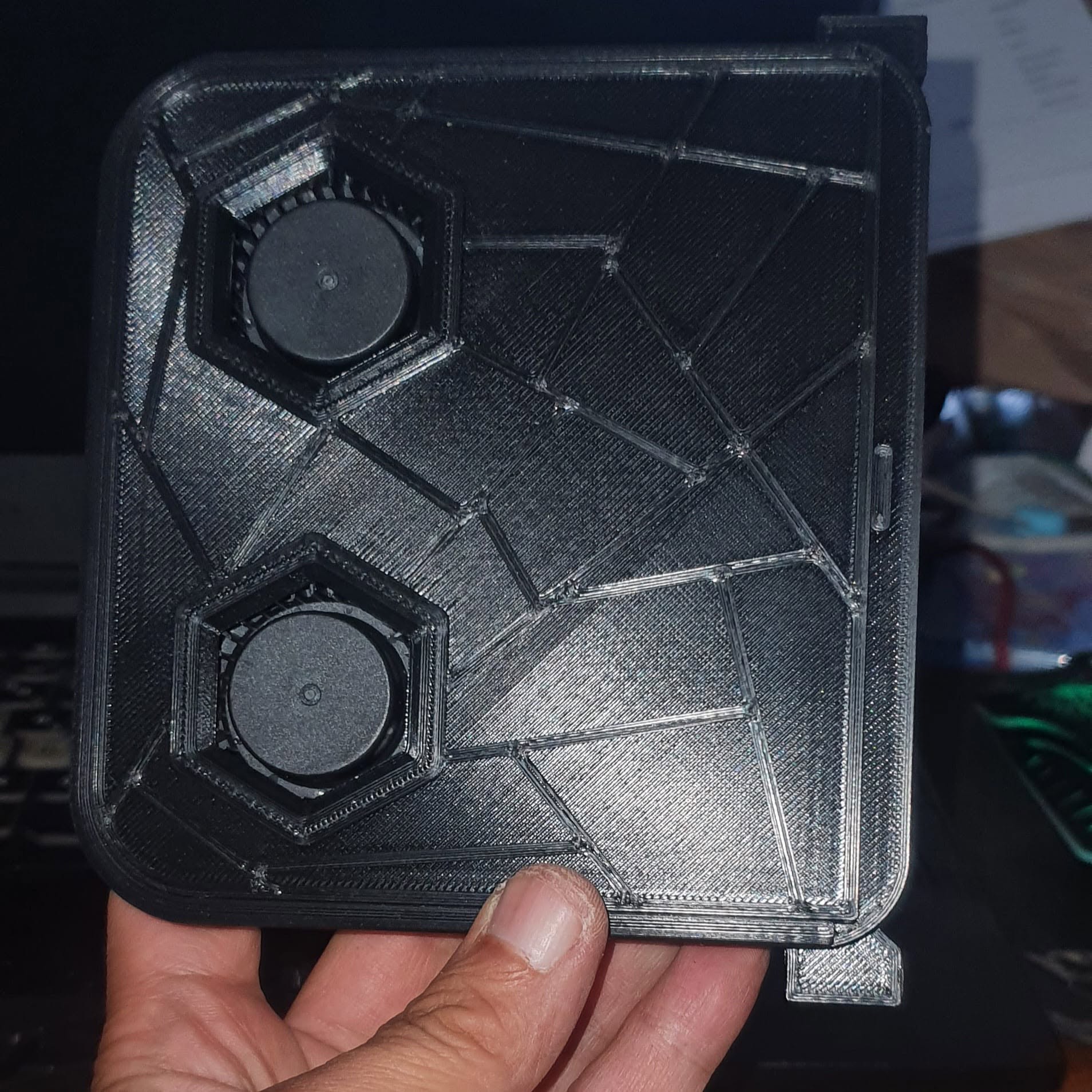
Recirculating Dual Fans Carbon Filter

28. Recirculating Dual Fans Carbon Filter

Initial mechanical build phase and framework alignment.

Toolhead Assembly And Wiring

29. Toolhead Assembly And Wiring

Initial mechanical build phase and framework alignment.

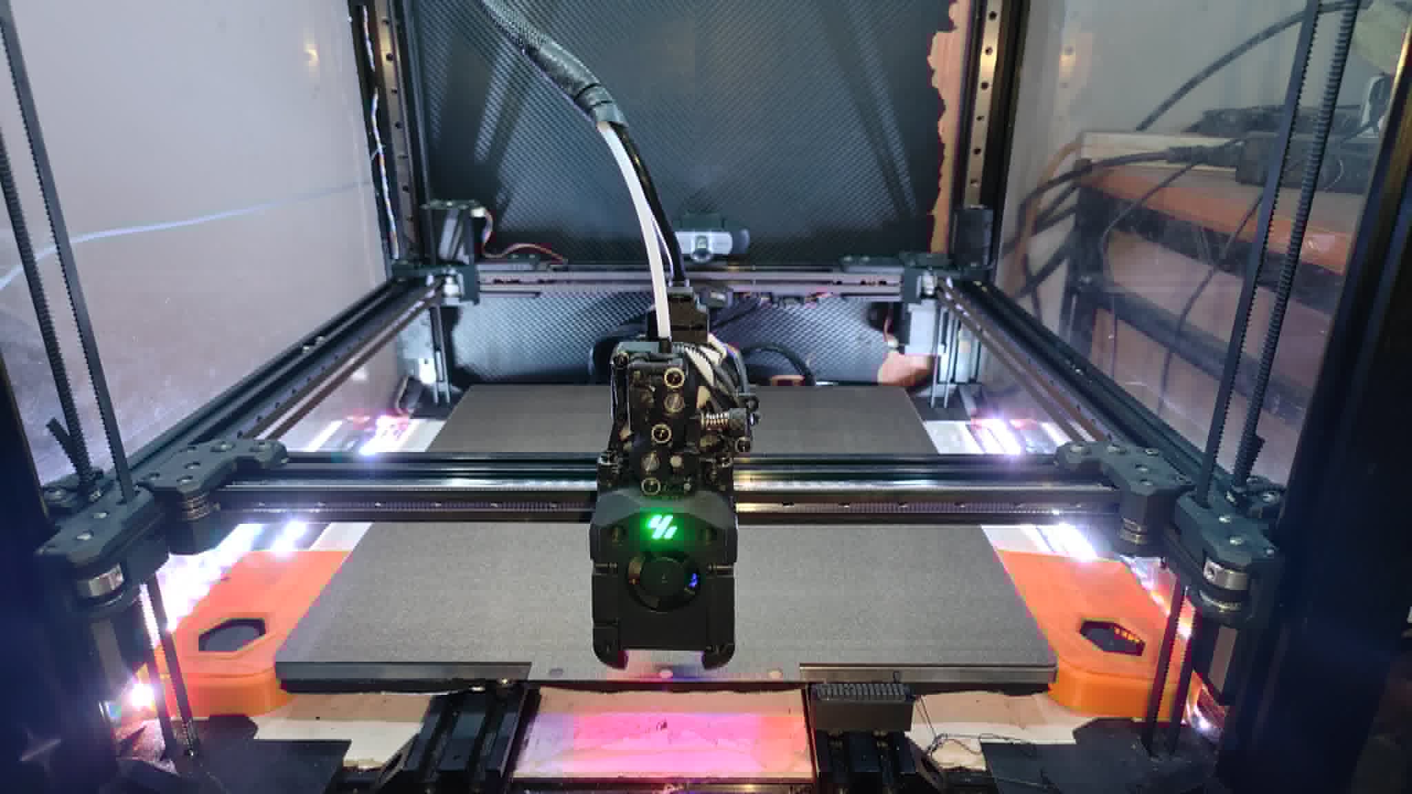
Toolhead Assembly Fitted

30. Toolhead Assembly Fitted

Initial mechanical build phase and framework alignment.

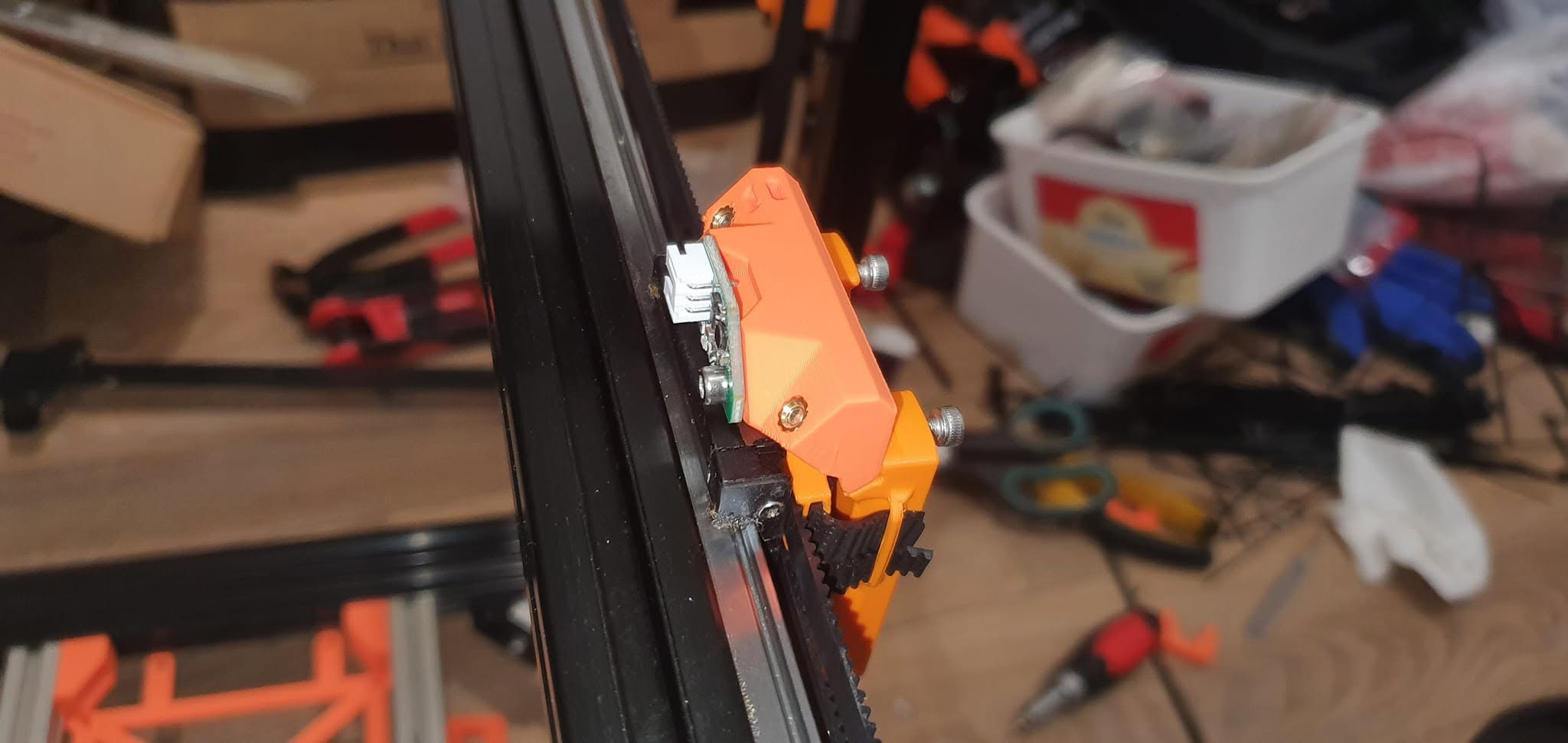
Toolhead Leveling Sensor Mounted

31. Toolhead Leveling Sensor Mounted

Initial mechanical build phase and framework alignment.

Top Frame With Corner Brackets

32. Top Frame With Corner Brackets

Initial mechanical build phase and framework alignment.

Top Mounted Web Cam

33. Top Mounted Web Cam

Initial mechanical build phase and framework alignment.

Top And Bottom Frame Assembly

34. Top And Bottom Frame Assembly

Initial mechanical build phase and framework alignment.

Under Side Electronics Fitted

35. Under Side Electronics Fitted

Initial mechanical build phase and framework alignment.

X Carriage With Toolhead Mount Fitted

36. X Carriage With Toolhead Mount Fitted

Initial mechanical build phase and framework alignment.

X Carraige With Belts Fitted

37. X Carraige With Belts Fitted

Initial mechanical build phase and framework alignment.

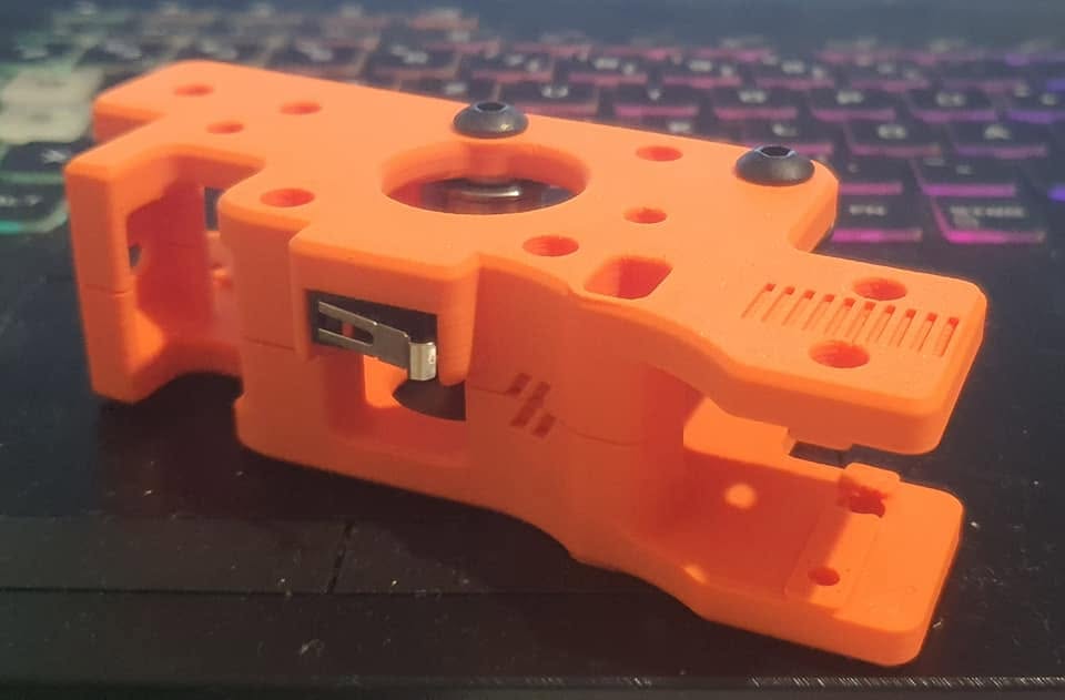
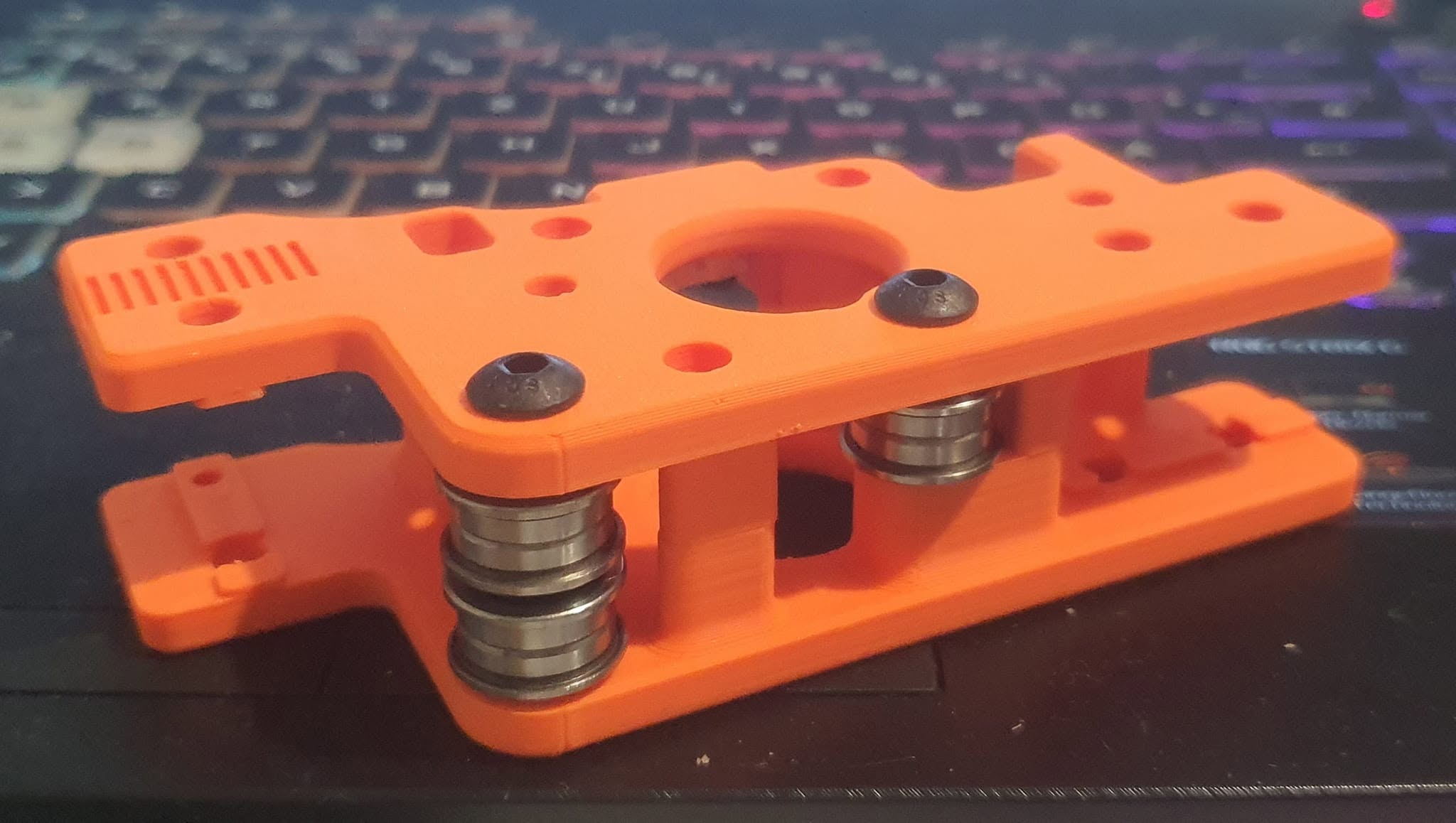
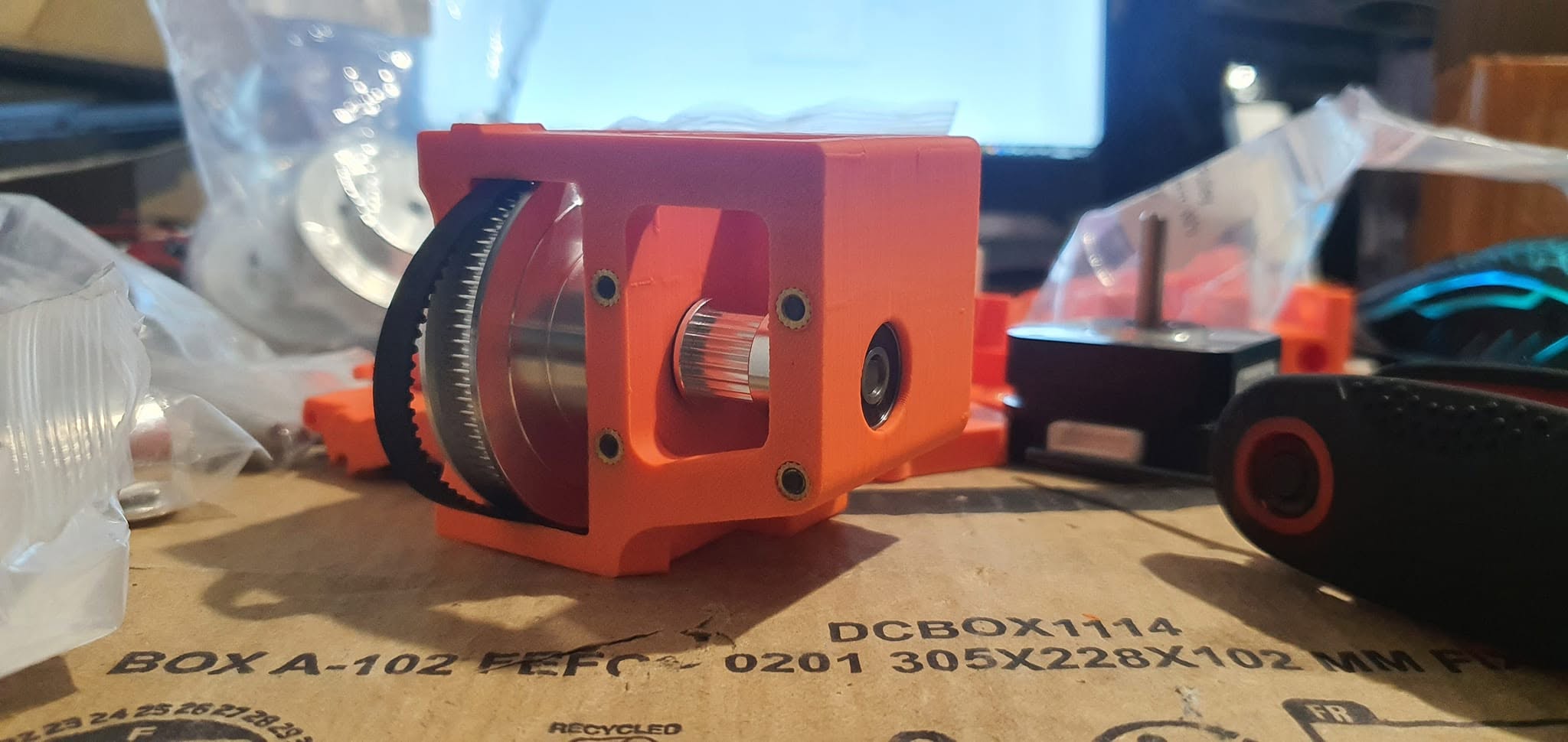
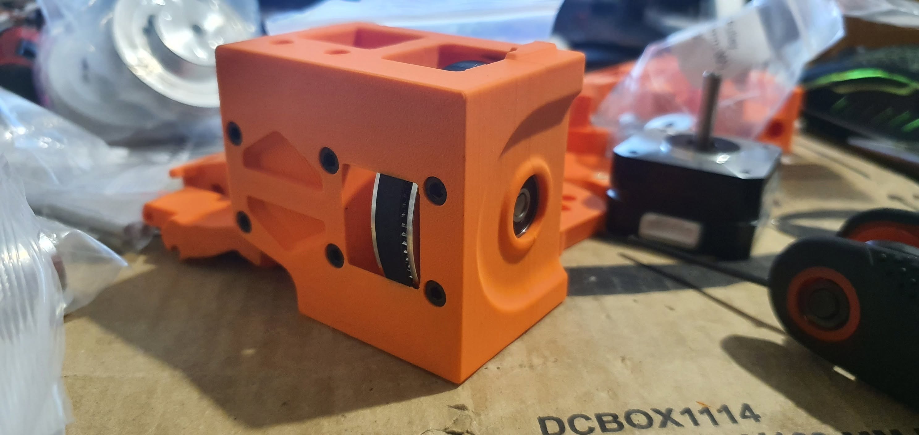
Z Axis Gearbox

38. Z Axis Gearbox

Initial mechanical build phase and framework alignment.

Z Axis Gearbox Printed

39. Z Axis Gearbox Printed

Initial mechanical build phase and framework alignment.

Z Axis Gearbox Rear

40. Z Axis Gearbox Rear

Initial mechanical build phase and framework alignment.

Thumbnail 1
Thumbnail 2
Thumbnail 3
Thumbnail 4
Thumbnail 5
Thumbnail 6
Thumbnail 7
Thumbnail 8
Thumbnail 9
Thumbnail 10
Thumbnail 11
Thumbnail 12
Thumbnail 13
Thumbnail 14
Thumbnail 15
Thumbnail 16
Thumbnail 17
Thumbnail 18
Thumbnail 19
Thumbnail 20
Thumbnail 21
Thumbnail 22
Thumbnail 23
Thumbnail 24
Thumbnail 25
Thumbnail 26
Thumbnail 27
Thumbnail 28
Thumbnail 29
Thumbnail 30
Thumbnail 31
Thumbnail 32
Thumbnail 33
Thumbnail 34
Thumbnail 35
Thumbnail 36
Thumbnail 37
Thumbnail 38
Thumbnail 39
Thumbnail 40
1 / 4

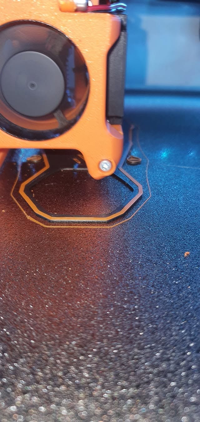
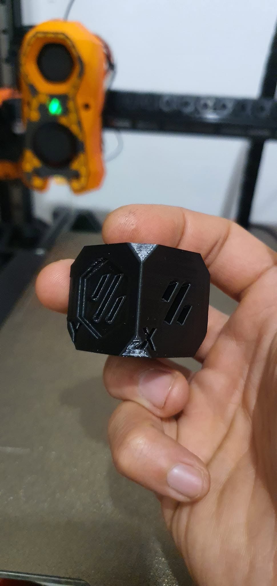
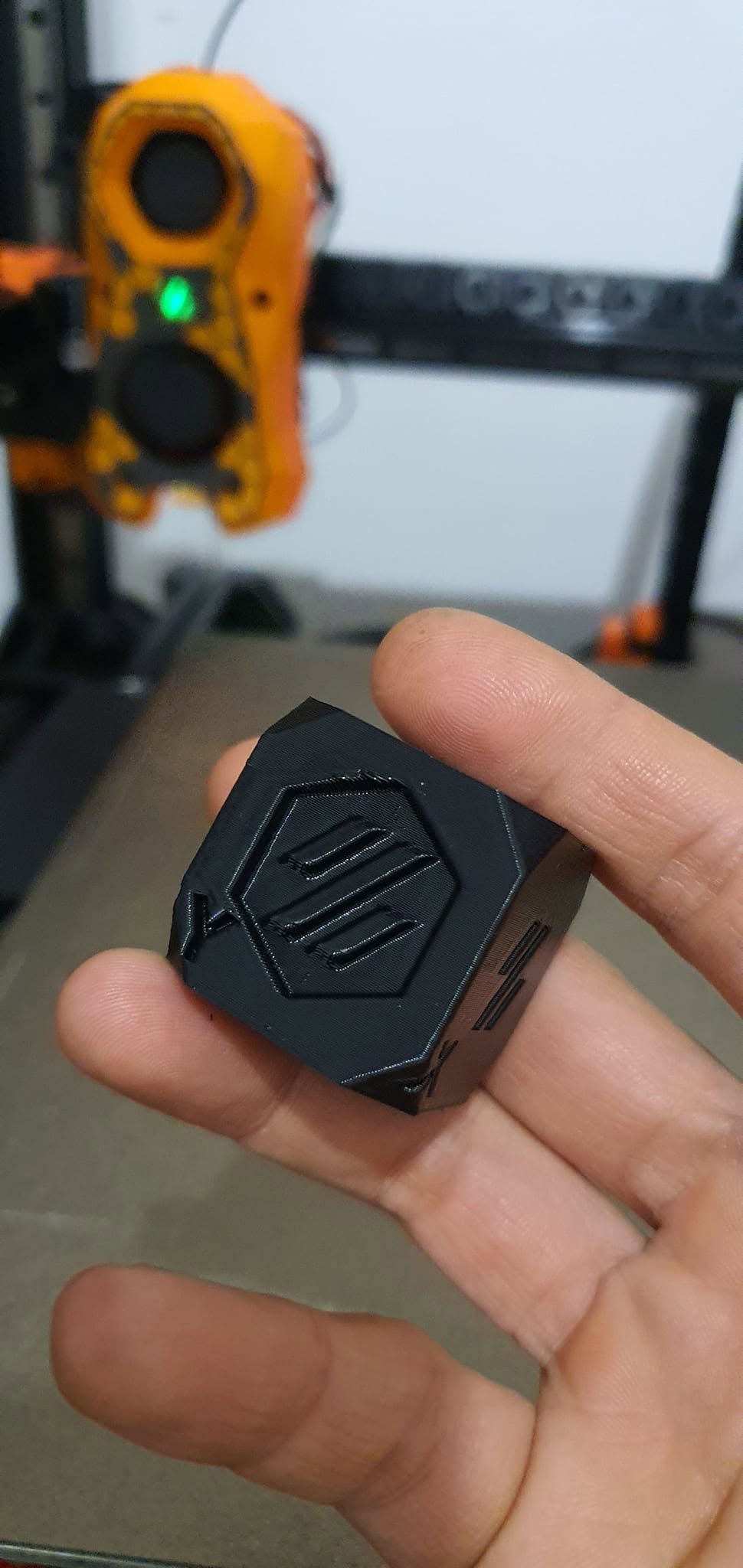
01. First Test Print

Phase 1 hardware test footage and kinematic response log.

02. Resonance Calibration

Phase 1 hardware test footage and kinematic response log.

03. Toolhead LED Installed

Phase 1 hardware test footage and kinematic response log.

04. Toolhead LED Testing

Phase 1 hardware test footage and kinematic response log.

1 / 10
CFGantry

01. CFGantry

Monolith gantry installation, GE5C joint alignment, and calibration stage.

Carbon Fiber Filled ASA Monolith Gantry

02. Carbon Fiber Filled ASA Monolith Gantry

Monolith gantry installation, GE5C joint alignment, and calibration stage.

Frame Design

03. Frame Design

Monolith gantry installation, GE5C joint alignment, and calibration stage.

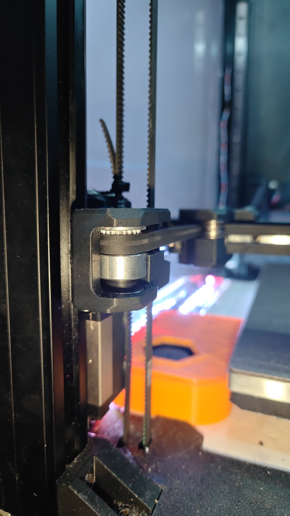
Front Idler With Double Shear Live Shaft Idler

04. Front Idler With Double Shear Live Shaft Idler

Monolith gantry installation, GE5C joint alignment, and calibration stage.

Motor Drive With Double Shear Live Idler

05. Motor Drive With Double Shear Live Idler

Monolith gantry installation, GE5C joint alignment, and calibration stage.

Reinforced Z Drive Mount CAD Drawing

06. Reinforced Z Drive Mount CAD Drawing

Monolith gantry installation, GE5C joint alignment, and calibration stage.

Reinforced Z Drive Mount CAD Drawing Inner Side

07. Reinforced Z Drive Mount CAD Drawing Inner Side

Monolith gantry installation, GE5C joint alignment, and calibration stage.

Reinforced Z Drive Mount Installed

08. Reinforced Z Drive Mount Installed

Monolith gantry installation, GE5C joint alignment, and calibration stage.

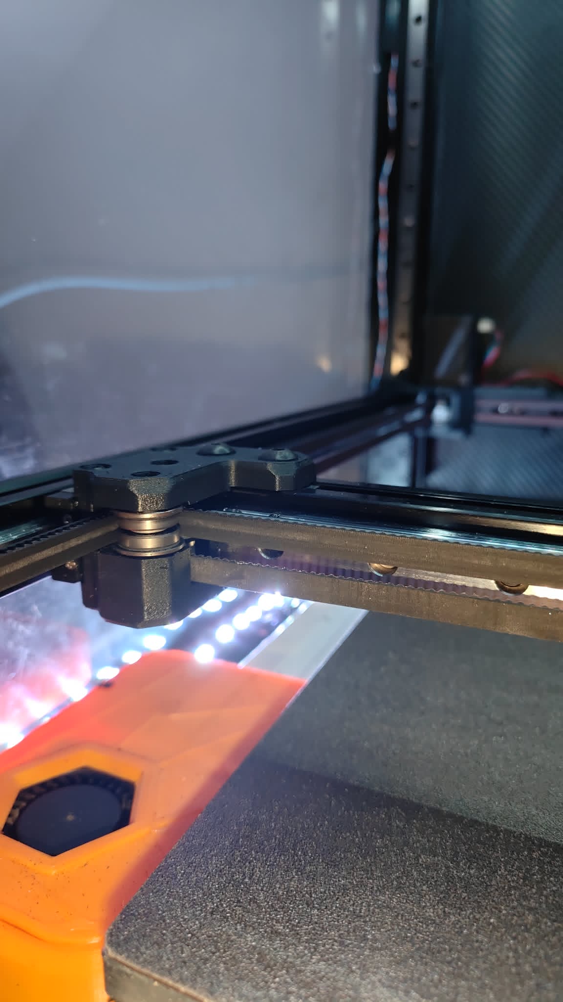
XY Axis Joint

09. XY Axis Joint

Monolith gantry installation, GE5C joint alignment, and calibration stage.

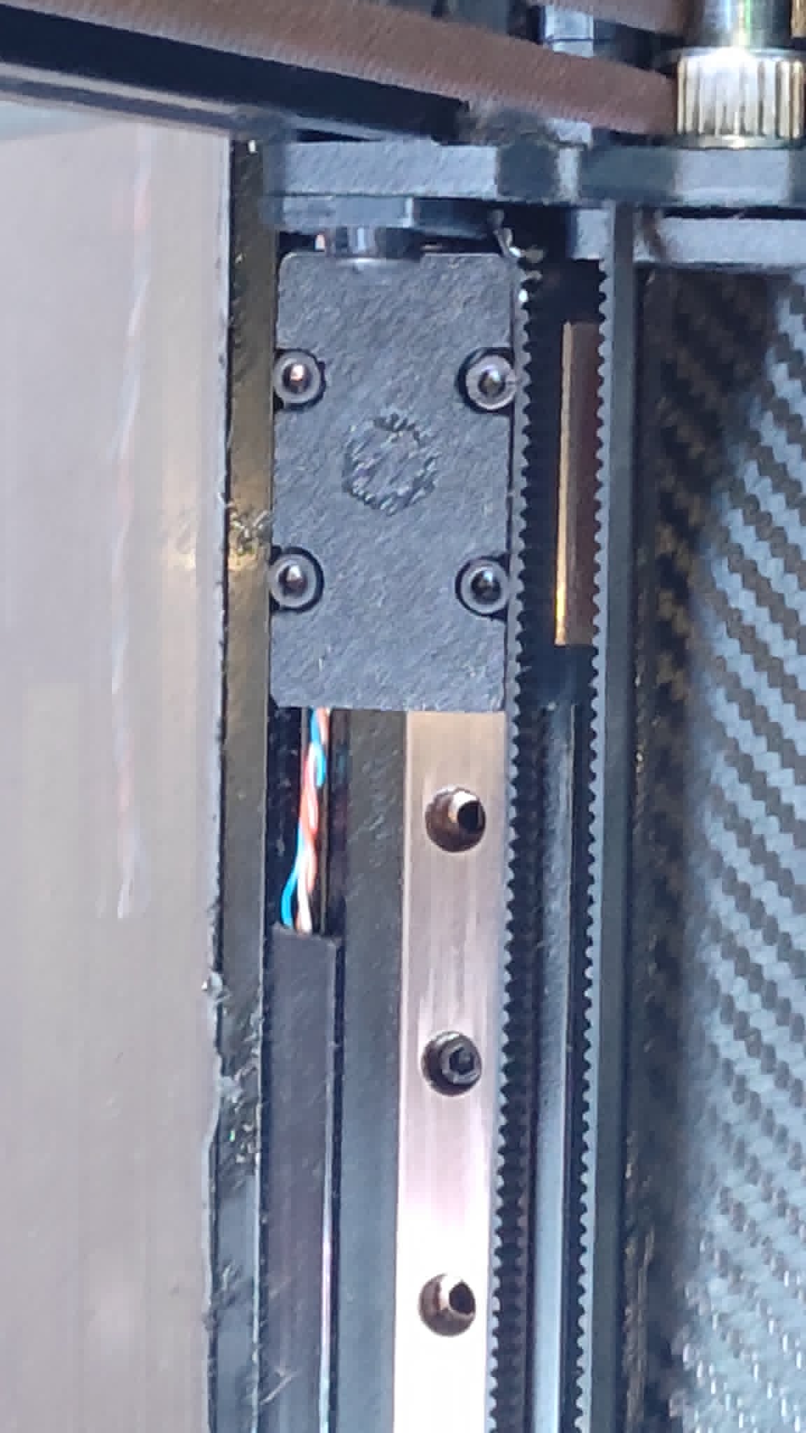
Z Axis Rail Joint With GE5C Bearing

10. Z Axis Rail Joint With GE5C Bearing

Monolith gantry installation, GE5C joint alignment, and calibration stage.

Thumbnail 1
Thumbnail 2
Thumbnail 3
Thumbnail 4
Thumbnail 5
Thumbnail 6
Thumbnail 7
Thumbnail 8
Thumbnail 9
Thumbnail 10
1 / 4

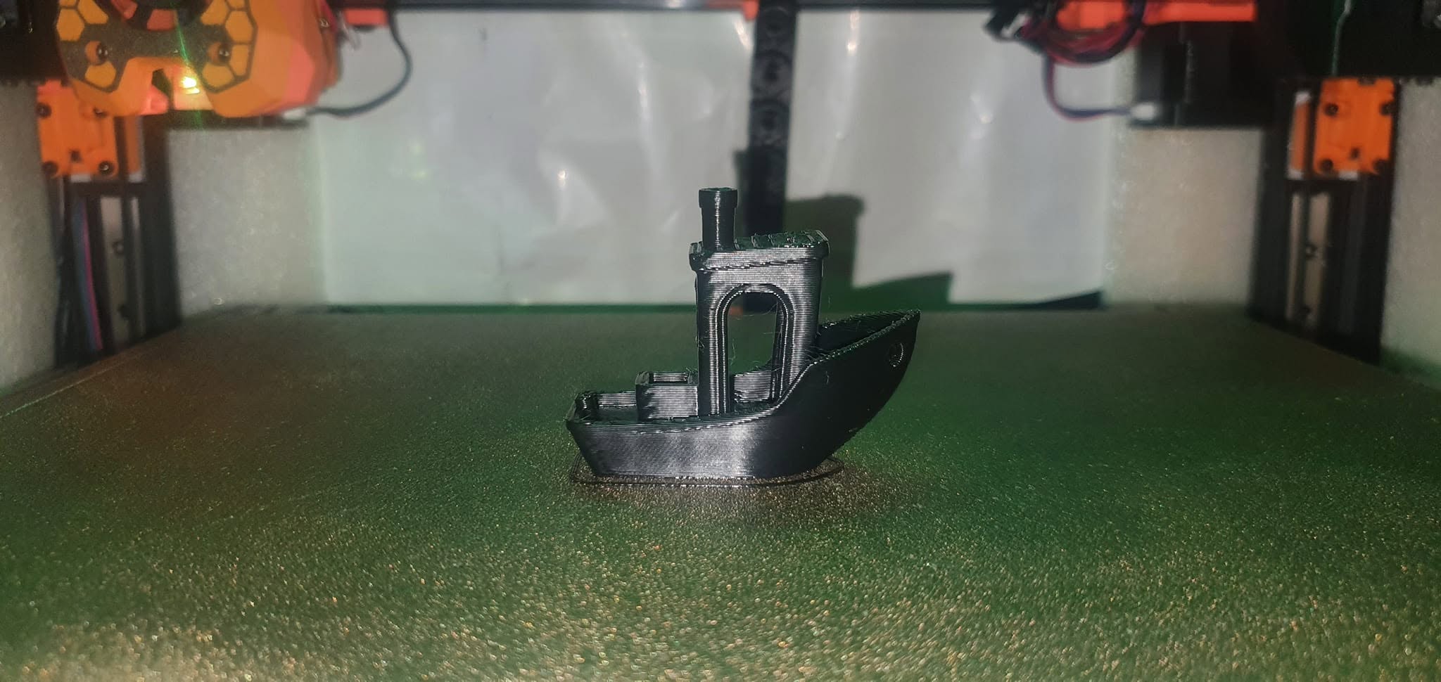
01. 9Mins 17sec Asa Benchy Vs Off The Shelf 1 Hour PLA Print

Phase 2 high-performance stress test and operational footage.

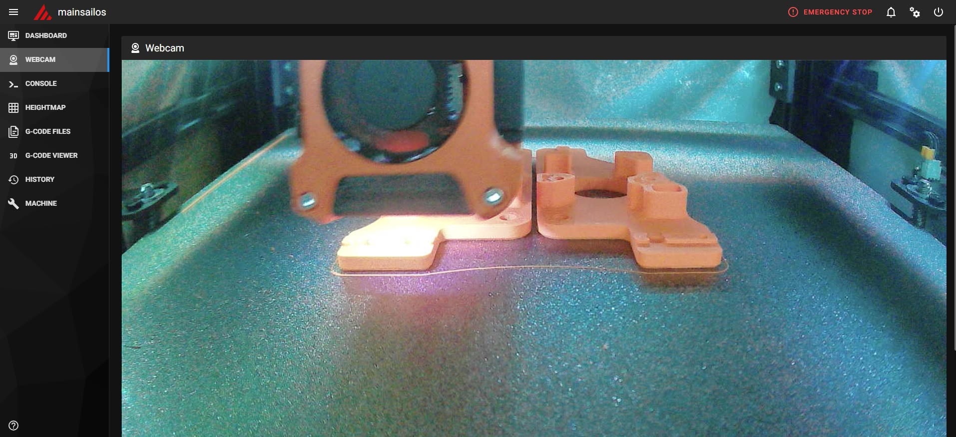
02. Printing New Z Drive Mount

Phase 2 high-performance stress test and operational footage.

03. Printing TPU Damper

Phase 2 high-performance stress test and operational footage.

04. Printing Z Drive Mount

Phase 2 high-performance stress test and operational footage.

Institutional Workshops & Educational Programs

What educational value do EIR3D school workshops provide?
Our workshops provide students with direct exposure to professional mechatronics, open-source programming, CAD design integration, electrical engineering safety, and high-performance manufacturing principles using commercial-grade machinery rather than simplified consumer kits.
What specific curriculum topics are covered during a session?
Sessions cover the complete engineering lifecycle: open-source firmware customization, structural mechanics, firmware tuning, high-voltage relay wiring safety, sensor integration (eddy current leveling), and advanced polymer material science.
How can educational institutions commission a workshop or demonstration?
Schools and technical training institutions can contact us directly via our booking page or email us at info@eir3d.com to arrange tailored curriculum demonstrations and workshop packages.